Sewage discharge equipment with heavy metal precipitation structure and operation method of sewage discharge equipment
A heavy metal precipitation and sewage discharge technology, applied in the direction of precipitation treatment, chemical instruments and methods, water/sewage multi-stage treatment, etc., can solve the problems of increasing labor force, long precipitation time, affecting sewage treatment efficiency, etc., to achieve enhanced practicability, The effect of reducing human labor and improving the efficiency of sewage treatment
- Summary
- Abstract
- Description
- Claims
- Application Information
AI Technical Summary
Problems solved by technology
Method used
Image
Examples
Embodiment 1
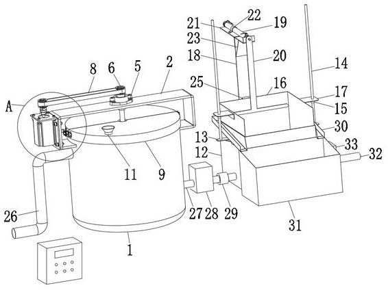
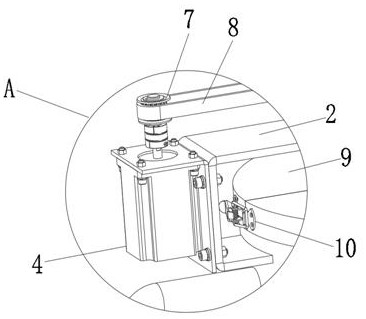
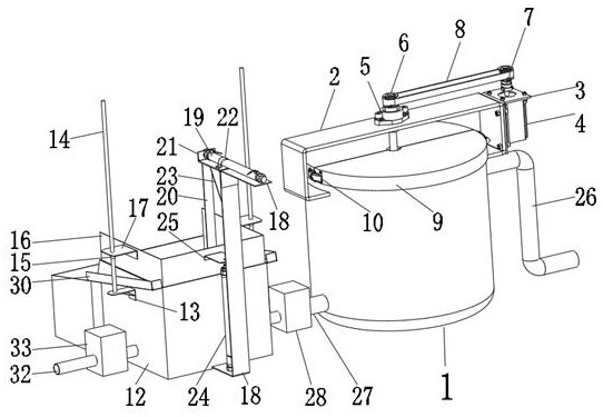
[0035] see Figure 1-10As shown, a sewage discharge device with a heavy metal precipitation structure includes a reaction tank 1 and a motor 4. A mounting plate 2 is fixedly connected to the outer wall of the reaction tank 1 near the top, and a second wall is fixedly connected to the side wall of the mounting plate 2. An L-shaped plate 3, the motor 4 is fixed on the side wall of the first L-shaped plate 3, the center position of the upper end surface of the mounting plate 2 is fixedly connected with a bearing 5 with a seat, and the bearing with a seat 5 is fixedly connected with a stirring shaft 6. The end of the output shaft of the motor 4 and the top of the stirring shaft 6 are fixedly connected with a synchronous wheel 7, and the two synchronous wheels 7 are connected by a synchronous belt 8. The top of the reaction tank 1 is provided with two sets of semicircular covers Plate 9, a settling tank 12 is arranged on one side of the reaction tank 1, and a second L-shaped plate ...
Embodiment 2
[0040] see Figure 1-10 As shown, a sewage discharge device with a heavy metal precipitation structure includes a reaction tank 1 and a motor 4. A mounting plate 2 is fixedly connected to the outer wall of the reaction tank 1 near the top, and a second wall is fixedly connected to the side wall of the mounting plate 2. An L-shaped plate 3, the motor 4 is fixed on the side wall of the first L-shaped plate 3, the center position of the upper end surface of the mounting plate 2 is fixedly connected with a bearing 5 with a seat, and the bearing with a seat 5 is fixedly connected with a stirring shaft 6. The end of the output shaft of the motor 4 and the top of the stirring shaft 6 are fixedly connected with a synchronous wheel 7, and the two synchronous wheels 7 are connected by a synchronous belt 8. The top of the reaction tank 1 is provided with two sets of semicircular covers Plate 9, a settling tank 12 is arranged on one side of the reaction tank 1, and a second L-shaped plate...
PUM
 Abstract
Description
Claims
Application Information
 - R&D
- Intellectual Property
- Life Sciences
- Materials
- Tech Scout
- Unparalleled Data Quality
- Higher Quality Content
- 60% Fewer Hallucinations
Browse by: Latest US Patents, China's latest patents, Technical Efficacy Thesaurus, Application Domain, Technology Topic, Popular Technical Reports.
© 2025 PatSnap. All rights reserved.Legal|Privacy policy|Modern Slavery Act Transparency Statement|Sitemap|About US| Contact US: help@patsnap.com


