Seismic mitigation and isolation frame structure, seismic mitigation and isolation damper and mounting method thereof

A frame structure and seismic isolation technology, applied in bridge parts, bridges, buildings, etc., can solve the problems of small initial stiffness of lead-core rubber bearings, easy to raise line elevation, and large space influence, and achieve clear force, The effect of prolonging the structure period and compact layout

Pending Publication Date: 2020-11-24
北京交达铁工科技有限公司 +1
View PDF0 Cites 0 Cited by
  • Summary
  • Abstract
  • Description
  • Claims
  • Application Information

AI Technical Summary

Problems solved by technology

From a technical point of view, these shock-absorbing and isolating devices have certain deficiencies, such as the initial stiffness of the lead rubber bearing is too small, and the vertical displacement of the friction pendulum bearing during operation tends to raise the line elevation, which has an impact on driving; The working life or durability of the hysteresis damper is a concern; the one-way force of the E-shaped steel and X-shaped steel damper makes the shock absorption and isolation limited by the directionality, and is affected by the space between the bottom of the beam and the top of the pier Big

Method used


Image

  • Seismic mitigation and isolation frame structure, seismic mitigation and isolation damper and mounting method thereof
  • Seismic mitigation and isolation frame structure, seismic mitigation and isolation damper and mounting method thereof
  • Seismic mitigation and isolation frame structure, seismic mitigation and isolation damper and mounting method thereof

Examples


Embodiment Construction

[0030] The present invention will be described below according to the embodiments shown in the accompanying drawings. It can be thought that embodiment disclosed this time is an illustration in every point, and is not restrictive. The scope of the present invention is not limited by the description of the following embodiments but only by the scope of the claims, and includes the same meaning as the scope of the claims and all modifications within the scope of the claims.

[0031] The shock-absorbing and isolating frame structure, the shock-absorbing and isolating damper and the installation method thereof involved in the present invention will be described in detail below in conjunction with the accompanying drawings.

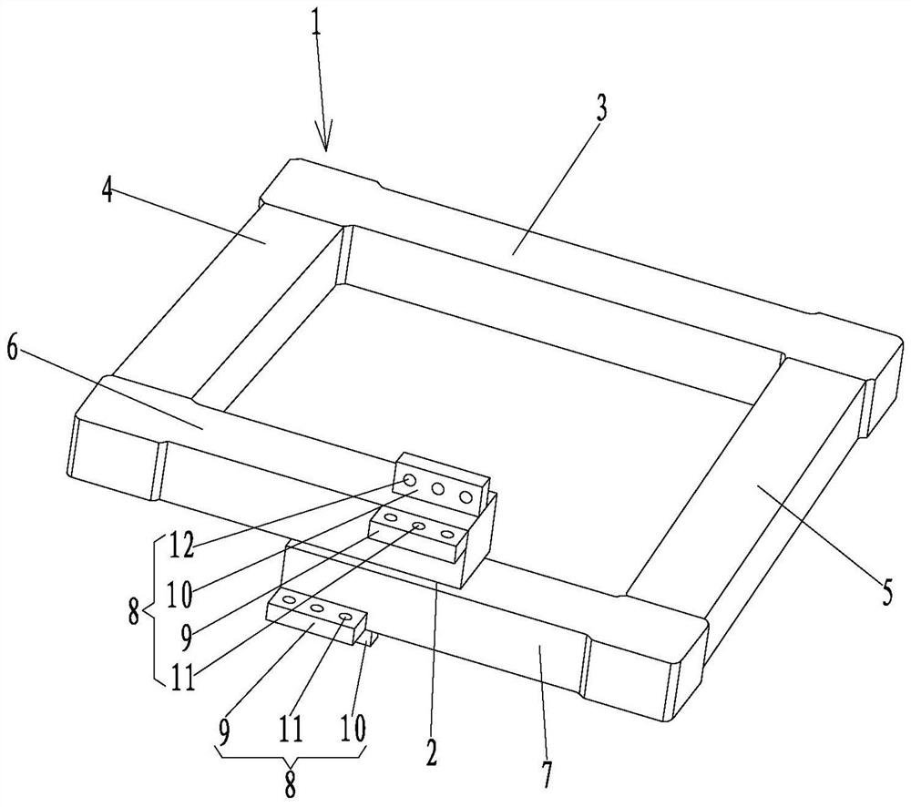
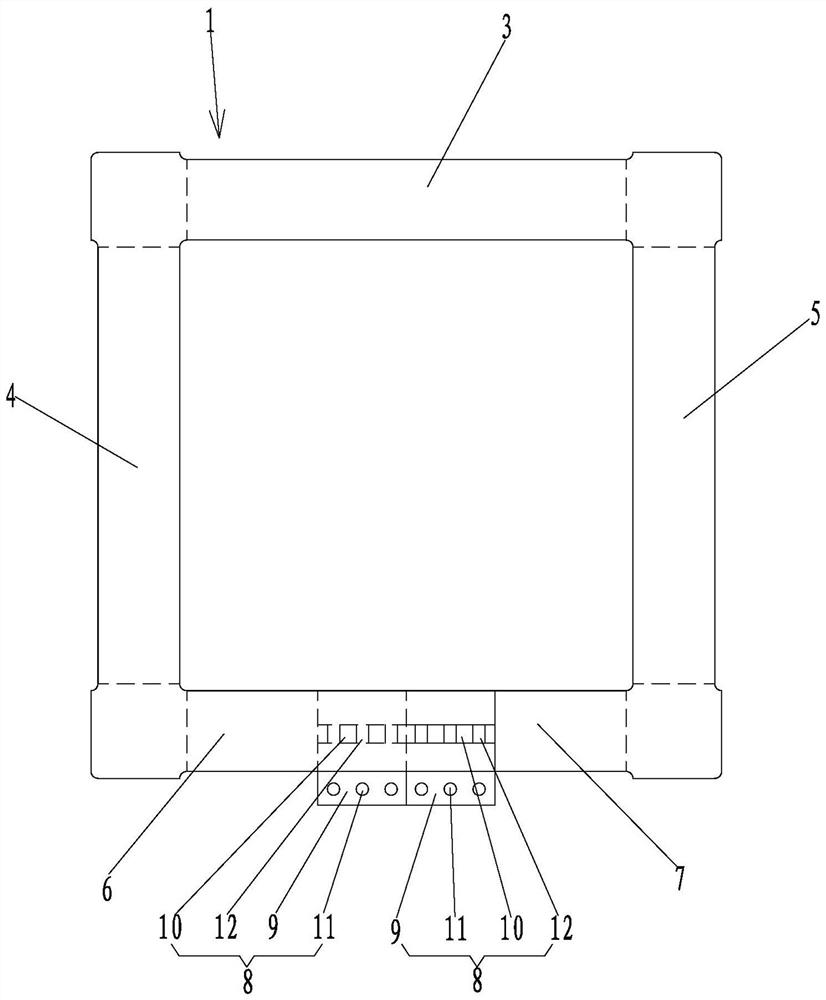
[0032] Such as figure 1 and figure 2 The three-dimensional structural schematic diagram and the top view structural schematic diagram of the embodiment of the shock-absorbing and isolating frame structure of the present invention are shown. The ends are se...


PUM


Abstract

The invention discloses a seismic mitigation and isolation frame structure, a seismic mitigation and isolation damper and a mounting method thereof. The seismic mitigation and isolation frame structure comprises a seismic mitigation and isolation frame, an opening is formed in the seismic mitigation and isolation frame, the two ends of the opening are arranged up and down, and force transmission connecting terminals are connected to the two ends correspondingly. The seismic mitigation and isolation damper comprises a support upper seat plate, a support lower seat plate and the seismic mitigation and isolation frame structure arranged between the support upper seat plate and the support lower seat plate, and the two force transmission connecting terminals are fixedly connected with the upper seat plate and the lower seat plate through detachable connecting pieces correspondingly. The mounting method of the seismic mitigation and isolation damper comprises the steps that the seismic mitigation and isolation frame is manufactured; the two force transmission connecting terminals are mounted at the opening of the seismic mitigation and absorption frame; and finally, the two force transmission connecting terminals are correspondingly connected with the support upper seat plate and the support lower seat plate. The damper is simple in structure, easy to manufacture, convenient to replace and not limited by the height of a support, energy dissipation and shock absorption can be achieved in any direction, a stable and higher damping ratio can be provided, and control over parameterssuch as horizontal free displacement, plastic deformation and the damping ratio can be achieved.

Description

technical field [0001] The invention relates to the technical field of vibration reduction and isolation of bridges, in particular to a vibration reduction and isolation frame structure, a vibration reduction and isolation damper and an installation method thereof. Background technique [0002] The bridge bearing is an important connecting device arranged between the superstructure and the substructure of the bridge. At present, spherical steel bearings and basin rubber bearings are widely used, but these two types of bearings do not have obvious shock absorption and isolation functions. [0003] In view of the damage to bridges caused by earthquakes, installing shock-absorbing and isolating devices or dampers between bridge girders and piers has become an important means of bridge shock-isolation design. [0004] Currently used shock absorbers include lead rubber bearings, high damping rubber bearings, friction pendulum bearings, viscous dampers, metal dampers, etc. Metal ...

Claims


Application Information

Patent Timeline
Patent Type & Authority Applications(China)
IPC IPC(8): E01D19/04
CPCE01D19/04
Inventor 李承根岳迎九高日赵会东吴延伟陈子衡杨少军康炜赵其光周友权李侠李歧高斯阳
Owner 北京交达铁工科技有限公司
Why Eureka
Try Eureka