A kind of drawing method of dynamometer diagram of reciprocating compressor

A compressor, reciprocating technology, applied in the field of drawing dynamometer diagrams, can solve the problems affecting the accuracy of the final result, affecting the realization of technical solutions, and high cost of technical realization, so as to broaden the scope of application, reduce monitoring costs, and achieve repeatability. strong effect

Active Publication Date: 2022-07-08
苏州德姆斯信息技术有限公司
View PDF0 Cites 1 Cited by
  • Summary
  • Abstract
  • Description
  • Claims
  • Application Information

AI Technical Summary

Problems solved by technology

[0006] However, it can be known from the above operation description that the existing technology has very significant shortcomings in the actual application process.
First of all, because the existing technology needs to disassemble some parts of the compressor to determine the dead center position of the piston before signal collection, if the number of compressors to be monitored is large, only this part of the work will cause huge manpower and material resources consume
Secondly, after determining the dead center position of the piston, there may be errors when marking the corresponding position of the flywheel, which will affect the accuracy of the final result
Finally, because the drawing and monitoring of the dynamometer diagram in the prior art needs to be completed with the help of two sensors, the technical implementation cost is relatively high; moreover, the coupling requirements of the two sensors are high when they work together, and the long-term running state of the compressor Under these conditions, any sensor may have unexpected problems, which will affect the realization of the entire technical solution

Method used


Image

  • A kind of drawing method of dynamometer diagram of reciprocating compressor
  • A kind of drawing method of dynamometer diagram of reciprocating compressor
  • A kind of drawing method of dynamometer diagram of reciprocating compressor

Examples


Embodiment Construction

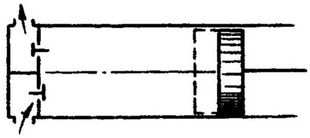
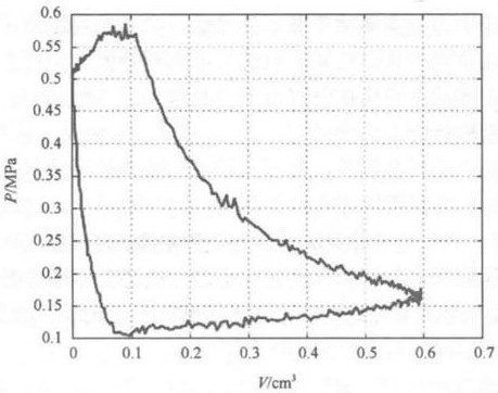
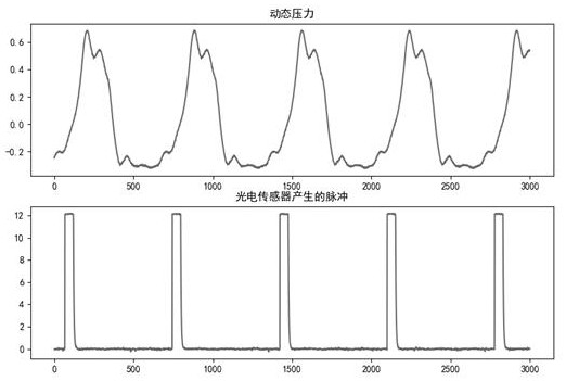
[0040]The invention discloses a method for drawing a dynamometer diagram of a reciprocating compressor by using single sensor data. The idea of ​​the invention is to use the dynamic pressure sensor to measure the pressure data of the reciprocating compressor in multiple working cycles, then identify and calculate the average number of pressure data points N included in each working cycle, and then randomly select the measured pressure data. Consecutive N points of pressure data are used to draw a dynamometer diagram (pressure displacement diagram) as a period of pressure data. The main operation of the present invention is to identify the crank angle corresponding to the pressure data of each point in the cycle, thereby calculating the displacement value of the piston, and then the dynamometer diagram can be drawn.

[0041] Specific plans such as Figure 4 As shown, the specific embodiments of the present invention will be further described in detail below in conjunction with...


PUM


Abstract

The invention discloses a method for drawing a dynamometer diagram of a reciprocating compressor, including: S1, determining a standard dynamometer diagram, and defining and acquiring various parameters; S2, measuring all pressures of multiple complete cycles of the reciprocating compressor running stably Signal data, calculate the average value of the data points of the compressor in each complete cycle; S3. Randomly select multiple consecutive data points in the pressure signal data to obtain the pressure signal data of the compressor in a complete cycle; S4. Create An arithmetic sequence, set the traversal of the crank angle corresponding to the first data point in the pressure signal data as the value in the sequence, obtain multiple speculative dynamometers, and calculate the similarity scores between them and the standard dynamometer respectively; S5 , Find a speculative indicator diagram with the highest similarity score, and use it as the actual indicator diagram. The invention only uses one sensor to complete the drawing of the dynamometer diagram, which not only reduces the monitoring cost of the enterprise, but also improves the accuracy of the final result.

Description

technical field [0001] The invention relates to a method for drawing a dynamometer diagram, in particular to a method for drawing a dynamometer diagram for a reciprocating compressor using single sensor data, and belongs to the field of mechanical equipment fault diagnosis. Background technique [0002] Common reciprocating compressor systems go through four processes when they work, combined with figure 1 The schematic diagram of the partial structure of the shown reciprocating compressor will be described. [0003] When the piston moves from right to left, the gas volume in the cylinder decreases and the pressure increases. This process is the "compression" process of the compressor; when the gas pressure increases to a certain level, the exhaust valve opens and the piston continues Moving to the left, the gas continues to be discharged until the piston moves to the outer dead center position (that is, the far left side of the cylinder shown in the figure), this process i...

Claims


Application Information

Patent Timeline
Patent Type & Authority Patents(China)
IPC IPC(8): F04B51/00
CPCF04B51/00
Inventor 邓刚张玉斌程攀勇
Owner 苏州德姆斯信息技术有限公司
Why Eureka
Try Eureka