Superfine metal composite fiber test fixture
A metal composite and test fixture technology, applied in the field of composite fiber processing, can solve problems such as difficult to judge the straight state of the fiber, affect the test effect, and the deviation between the fiber and the center point, etc., to facilitate observation, ensure the test effect, and increase friction Effect
- Summary
- Abstract
- Description
- Claims
- Application Information
AI Technical Summary
Problems solved by technology
Method used
Image

Examples
Embodiment 1
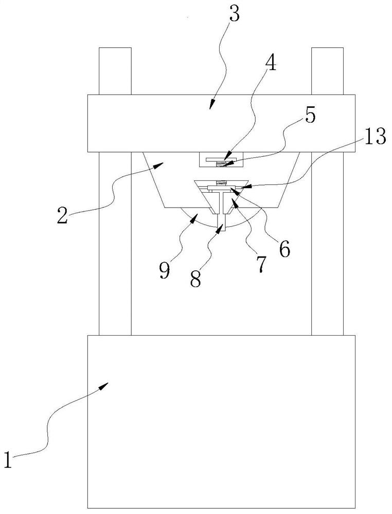
[0029] Such as Figure 1 to Figure 8 shown;
[0030] figure 1 It is a structural schematic diagram of the present invention;
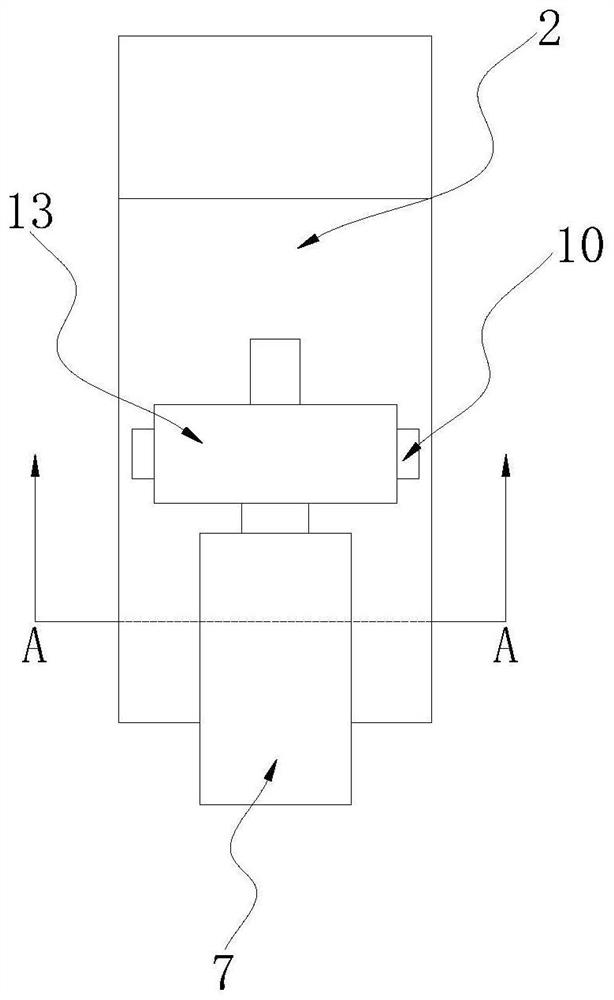
[0031] figure 2 It is a schematic diagram of the structure between the inserting board and the clamping block in the present invention;
[0032] image 3 It is a schematic diagram of the structure between the clamp block and the mounting seat in the present invention;
[0033] Figure 4 It is a schematic diagram of the structure between the connecting board and the inserting board in the present invention;
[0034] Figure 5 It is a schematic diagram of the structure between the mounting base and the protractor in the present invention;
[0035] Figure 6 It is a structural schematic diagram of a protractor in the present invention;
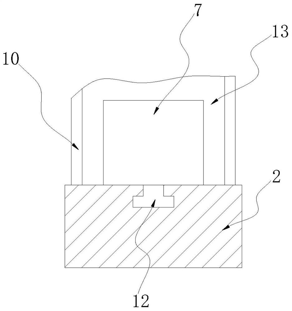
[0036] Figure 7 It is an enlarged view of A place in the present invention;
[0037] Figure 8 It is a structural schematic diagram of clamping block in the present invention.
[0038] An ultra-fine metal ...
PUM
 Abstract
Description
Claims
Application Information
 - Generate Ideas
- Intellectual Property
- Life Sciences
- Materials
- Tech Scout
- Unparalleled Data Quality
- Higher Quality Content
- 60% Fewer Hallucinations
Browse by: Latest US Patents, China's latest patents, Technical Efficacy Thesaurus, Application Domain, Technology Topic, Popular Technical Reports.
© 2025 PatSnap. All rights reserved.Legal|Privacy policy|Modern Slavery Act Transparency Statement|Sitemap|About US| Contact US: help@patsnap.com