
Thermal neutron transmission imaging method and imaging device based on compact D-D neutron source

An imaging device, thermal neutron technology, applied in the use of radiation for material analysis, etc., can solve the problems of damage to neutron position resolution, high gamma background, low position resolution, etc., and achieve the effect of good spatial resolution

Pending Publication Date: 2020-11-24
LANZHOU UNIVERSITY
View PDF10 Cites 5 Cited by
  • Summary
  • Abstract
  • Description
  • Claims
  • Application Information

AI Technical Summary

Problems solved by technology

[0004] The problems existing in the existing technology are: the existing thermal neutron transmission imaging systems are all based on the thermal neutron field provided by the reactor neutron source, but the reactor neutron source has complex structure, high γ background, huge operating system and high cost , expensive operation and maintenance costs, immovable and other defects
Therefore, the reactor-based thermal neutron transmission imaging system is difficult to apply to the transmission detection requirements of materials in the fields of industrial manufacturing, aerospace, ships, etc.
Secondly, the existing thermal neutron transmission imaging detectors use thermal neutron fluorescence conversion screen or thermal neutron sensitive microchannel plate (MCP) device, its working principle is that thermal neutrons are converted into charged particles, electrons are multiplied in MCP, It is converted into optical signals through the fluorescent conversion screen, and the optical signals are collected to obtain the information of transmitted neutrons. The three conversions of transmitted neutrons seriously damage the position resolution of neutrons, making the position resolution of the whole system lower.

Method used


Image

  • Thermal neutron transmission imaging method and imaging device based on compact D-D neutron source
  • Thermal neutron transmission imaging method and imaging device based on compact D-D neutron source
  • Thermal neutron transmission imaging method and imaging device based on compact D-D neutron source

Examples


Embodiment Construction

[0020] In order to make the object, technical solution and advantages of the present invention clearer, the present invention will be further described in detail below in conjunction with the accompanying drawings and embodiments. It should be understood that the specific embodiments described here are only used to explain the present invention, not to limit the present invention.

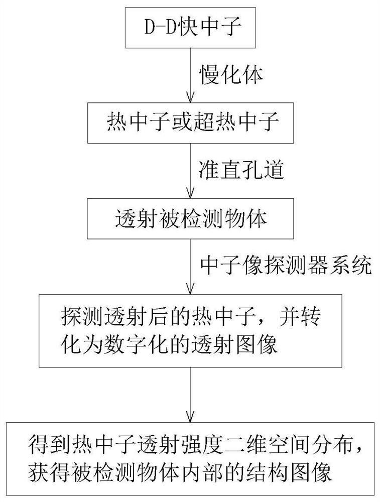
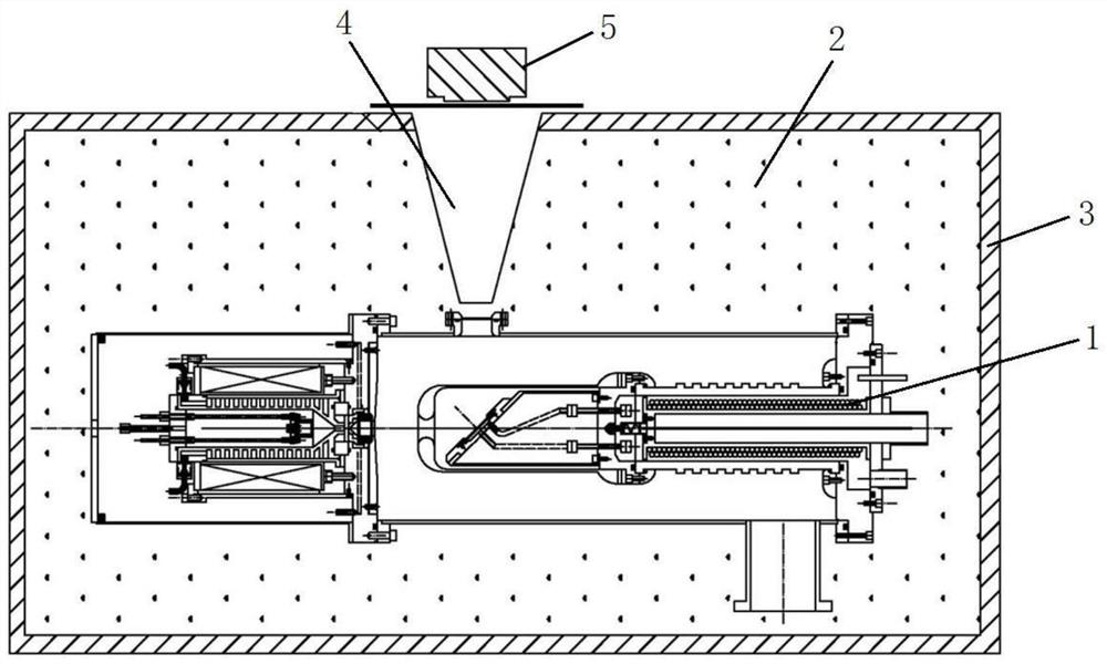
[0021] The invention provides a thermal neutron transmission imaging method based on a compact D-D neutron source, the flow chart refers to figure 1 , using a compact D-D neutron source to provide external neutrons, and its D-D neutron yield is greater than 10 9 n / s, the neutron output stability is better than 99%. The 2.45MeV D-D fast neutrons output by the compact D-D neutron source are moderated by neutron moderators to thermal neutrons or epithermal neutrons. The final thermal neutrons or epithermal neutrons enter the conical neutron collimation channel, the collimated thermal neutron beam tra...


PUM

PropertyMeasurementUnit
thicknessaaaaaaaaaa

Abstract

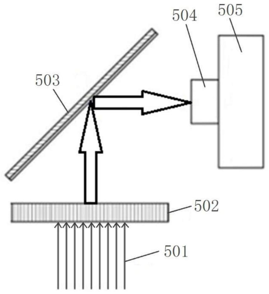
The invention discloses a thermal neutron transmission imaging method and imaging device based on a compact D-D neutron source. The compact D-D neutron source is adopted to provide exogenous neutrons;2.45 MeV D-D fast neutrons outputted by the D-D neutron source are moderated into thermal neutrons or epithermal neutrons through the neutron moderator; after being slowed down, the neutrons enter abig-end-up conical neutron collimation hole channel vertically formed in a neutron slowdown body above a D-D neutron source; the collimated thermal neutron beam transmits a detected object; thermal neutrons penetrating through an object in a transmission mode are detected through the thermal neutron image detector system installed at the upper end of the conical neutron collimation hole channel, the thermal neutrons are converted into digital transmission images through the thermal neutron image detector system, two-dimensional spatial distribution of thermal neutron transmission intensity isobtained, and then the internal structure of the detected object and the spatial distribution situation of different materials are obtained. The method has the characteristics of mobility, rapidness,accuracy, no damage and good spatial resolution, and can be used for nondestructive detection of objects.

Description

technical field [0001] The invention belongs to the technical field of non-destructive detection of objects, and in particular relates to a thermal neutron transmission imaging method and imaging device based on a compact D-D neutron source. Background technique [0002] Neutron photography in a broad sense includes neutron transmission imaging, neutron tomography imaging, neutron resonance imaging, neutron polarization imaging, neutron phase imaging, neutron holographic imaging, neutron small angle scattering imaging, neutron coding imaging and Neutron Phase Imaging, etc. Similar to common X-ray imaging, neutron radiography is an imaging method that uses the intensity changes caused by scattering or absorption when neutron beams penetrate objects to obtain information such as the structure and internal defects of the object being irradiated. A non-destructive testing technique with potential application value. The sensitivity of neutrons to various elements is significant...

Claims


Application Information

Patent Timeline
Patent Type & Authority Applications(China)
IPC IPC(8): G01N23/05G01N23/09
CPCG01N23/05G01N23/09
Inventor 韦峥姚泽恩张宇马占文黑大千王俊润徐大鹏卢小龙
Owner LANZHOU UNIVERSITY
Learn More