Sliding door guide rail arrangement method and system

A layout method and sliding door technology, applied in the field of vehicle engineering, can solve the problems of high risk of sliding door design, overturning the original style or design and influence of the sliding door, so as to reduce the cost of development and verification, reduce the design risk, The effect of shortening the development cycle

Pending Publication Date: 2020-11-24
SAIC MOTOR
View PDF3 Cites 1 Cited by
  • Summary
  • Abstract
  • Description
  • Claims
  • Application Information

AI Technical Summary

Problems solved by technology

The current sliding door guide rail layout method is to first use CATIA software to analyze the kinematics of the three guide rails arranged in the previous stage, and then directly apply the guide rail layout scheme that satisfies the kinematic analysis to the actual car manufacturing process, and then only use soft film to build cars and Slam and other actual tests to further verify whether the guide rail layout of the sliding door meets the requirements in the early stage, resulting in a high risk in the design of the sliding door, which needs to be revised repeatedly in the actual car manufacturing process, thus making the development and verification of the sliding door costly and difficult for project development. Long cycle issues that may even affect the original molding style or design that would overturn the sliding door

Method used


Image

  • Sliding door guide rail arrangement method and system
  • Sliding door guide rail arrangement method and system
  • Sliding door guide rail arrangement method and system

Examples


Embodiment Construction

[0045]The following will clearly and completely describe the technical solutions in the embodiments of the application with reference to the drawings in the embodiments of the application. Apparently, the described embodiments are only some of the embodiments of the application, not all of them. Based on the embodiments in this application, all other embodiments obtained by persons of ordinary skill in the art without making creative efforts belong to the scope of protection of this application.

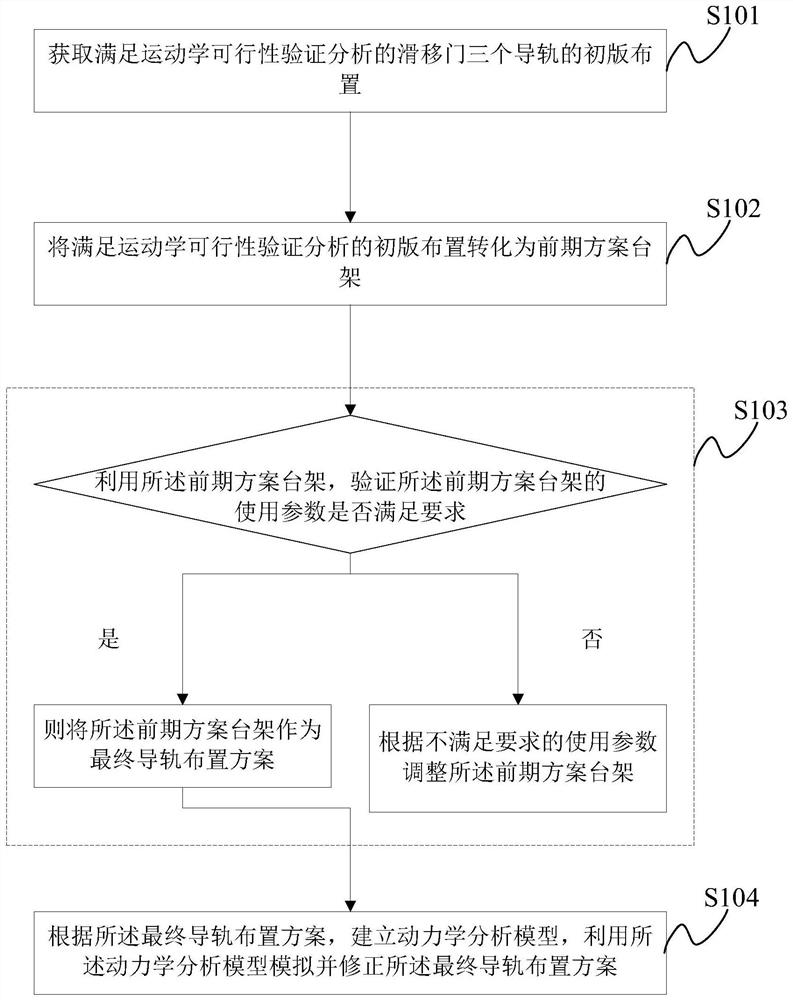
[0046] The embodiment of the present application provides a sliding door guide rail arrangement method, such as figure 1 shown, including:

[0047] S101: Obtain the first version of the layout of the three guide rails of the sliding door that satisfies the kinematics feasibility verification analysis;

[0048] S102: transforming the layout of the first version that satisfies the kinematic feasibility verification analysis into a pre-plan platform, the steps of the pre-plan include t...


PUM


Abstract

The invention discloses a sliding door guide rail arrangement method and system. The sliding door guide rail arrangement method comprises the following steps: obtaining primary arrangement meeting kinematics feasibility verification analysis; converting the primary layout into an early-stage scheme rack; the early-stage scheme rack is utilized; verifying whether the use parameters of the early-stage scheme rack of the primary layout comprising the three guide rails meet the requirements or not; the early-stage scheme rack meeting the requirements is used as a final guide rail arrangement scheme; finally, according to the final guide rail arrangement scheme; establishing a kinetic analysis model, and simulating and correcting the final guide rail arrangement scheme by utilizing the kineticanalysis model. Therefore, the purpose of verifying the use parameters of the determined final guide rail arrangement scheme before actual vehicle manufacturing is achieved, the design risk of the sliding door is reduced, the situation of repeated modification in the actual vehicle manufacturing process is avoided, the development and verification cost of the sliding door is reduced, and the development period of a sliding door project is shortened.

Description

technical field [0001] The present application relates to the technical field of vehicle engineering, and more specifically, to a sliding door guide rail arrangement method and system. Background technique [0002] The sliding door refers to the door that mainly moves in the direction parallel to the side of the motor vehicle body during the door opening and closing process. The sliding door has the advantage of not occupying a large outside area of ​​the vehicle after opening, and can better avoid the door from being opened outwards. Possible collisions with pedestrians. [0003] In the development process of the sliding door, how to balance the arrangement angle and spatial position relationship of the upper, middle and lower guide rails of the sliding door is a major problem that plagues those skilled in the art. Whether the arrangement of the upper, middle and lower guide rails of the sliding door is reasonable directly affects the kinematics and dynamics of the sliding...

Claims


Application Information

Patent Timeline
Patent Type & Authority Applications(China)
IPC IPC(8): G06F30/15G06F30/20B62D65/00G06F119/14
CPCB62D65/00
Inventor 赵广生王武倪建华刘海玲李连好殷钢夏连张琦郑剑飞王富春张川段向雷
Owner SAIC MOTOR
Why Eureka
Try Eureka