Eureka AIR delivers breakthrough ideas for toughest innovation challenges, trusted by R&D personnel around the world.

Centralized energy storage equipment thermal management system and working method thereof

A thermal management system and technology for energy storage equipment, applied in the field of thermal management systems for centralized energy storage equipment, can solve the problems of unsuitable large-scale power station battery energy storage systems, unified management of temperature control and fire protection, complex system structure, etc., and achieve Improve security and stability, reduce unexpected security problems, and achieve high degree of automation

Active Publication Date: 2020-11-24
HUANENG CLEAN ENERGY RES INST +2
View PDF10 Cites 0 Cited by
  • Summary
  • Abstract
  • Description
  • Claims
  • Application Information

AI Technical Summary

Problems solved by technology

[0004] At present, the energy storage battery thermal management system mainly adopts air cooling, liquid cooling, phase change material cooling or several methods of coupling. These methods have disadvantages such as complex system structure and high system energy consumption. However, the relatively mature liquid cooling system is not It is suitable for large-scale power station battery energy storage systems. This is mainly because the battery energy storage system accumulates a large number of batteries in a certain space, and the unified management of temperature control and fire protection cannot be achieved uniformly, which will cause high energy consumption and high cost of the system. no problem

Method used


Image

  • Centralized energy storage equipment thermal management system and working method thereof
  • Centralized energy storage equipment thermal management system and working method thereof
  • Centralized energy storage equipment thermal management system and working method thereof

Examples


Embodiment Construction

[0031] The present invention will be described in further detail below in conjunction with accompanying drawing, and its content is explanation of the present invention rather than limitation:

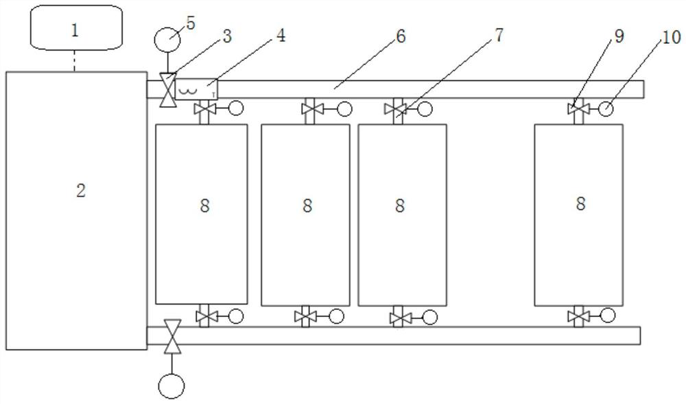
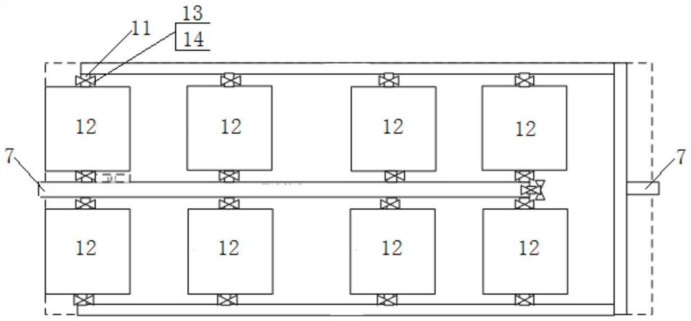
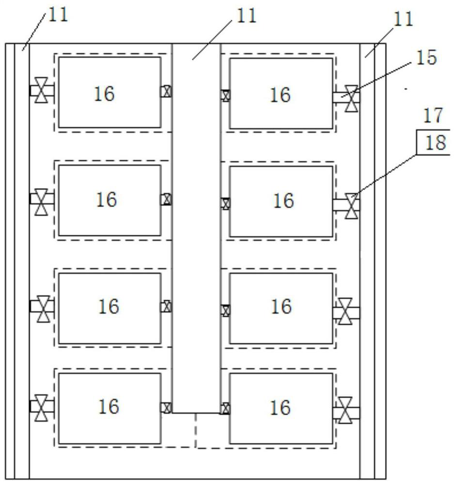
[0032] In the thermal management system of the centralized energy storage device of the present invention, the main circulation road 6 is connected to the main water tank 2, the main circulation water pump 3 is provided on the main circulation road 6, and the main road water pump 3 is connected with the pressure flow detection unit 4 and the temperature measurement of the main road Unit 5; the circulation main road 6 is connected with several circulation branches 7, each circulation branch 7 is connected with an energy storage container 8, the circulation branch 7 is provided with a branch water pump 9, and the branch water pump 9 is connected with a branch test The temperature unit 10; the circulation branch 7 is connected with several circulation branches 11, each circulation branch 1...


PUM


Abstract

The invention discloses a centralized energy storage equipment thermal management system and a working method thereof, and belongs to the technical field of energy storage. A main controller is directly connected with a water pump and temperature measuring points of each stage in an energy storage system, centralized management and control are conducted on heat management of distributed energy storage units, a heat management mechanism of a single energy storage unit is omitted, energy consumption of the energy storage system is effectively reduced, and the design, installation and maintenancecost of the system is reduced. Through the real-time communication state information of each monitoring point in each stage of the energy storage system, the environment temperature of each stage inthe energy storage system is accurately controlled; and forced separation and cooling can be carried out when a certain energy storage unit is in a sudden thermal runaway state, so that the occurrenceprobability of sudden safety problems is reduced, huge economic losses caused by thermal runaway of the energy storage system are reduced, and the safety and stability of the energy storage system are improved.

Description

technical field [0001] The invention belongs to the technical field of energy storage, and in particular relates to a thermal management system of a centralized energy storage device and a working method thereof. Background technique [0002] When analyzing the energy storage process, some objects or space ranges drawn in order to determine the research object are called energy storage systems. It includes energy and material input and output, energy conversion and storage equipment. An energy storage system often involves multiple energies, multiple devices, multiple substances, and multiple processes. It is a complex energy system that changes with time, and requires multiple indicators to describe its performance. Commonly used evaluation indicators include energy storage density, energy storage power, energy storage efficiency, energy storage price, and environmental impact. [0003] Electrochemical energy storage refers to various secondary battery energy storage. It...

Claims


Application Information

Patent Timeline
Patent Type & Authority Applications(China)
IPC IPC(8): H01M10/613H01M10/635H01M10/6567H01M10/6568H01M10/48H01M10/42
CPCH01M10/613H01M10/486H01M10/635H01M10/425H01M10/4285H01M10/6567H01M10/6568H01M2010/4278Y02E60/10
Inventor 朱连峻刘大为刘明义朱耿锋孙超李萌李海建
Owner HUANENG CLEAN ENERGY RES INST
Why Eureka
Eureka Blog
Learn More