Flexible rotor based on active magnetic suspension bearing

A magnetic suspension bearing and flexible rotor technology, applied in the directions of magnetic bearings, bearings, shafts and bearings, can solve problems such as stuck, asymmetric magnetic gap and auxiliary gap, low damping, etc., to prevent friction and heat generation, avoid severe friction , to avoid the effect of displacement

Inactive Publication Date: 2020-11-24
江苏联博精密科技股份有限公司
View PDF0 Cites 0 Cited by
  • Summary
  • Abstract
  • Description
  • Claims
  • Application Information

AI Technical Summary

Problems solved by technology

[0002] Magnetic suspension bearings use magnetic force to suspend the rotor in the air, so that there is no mechanical contact between the rotor and the stator. The principle is that the magnetic induction line is perpendicular to the magnetic floating line, and the shaft core is parallel to the magnetic floating line, so the weight of the rotor is fixed in the running position. On the track, the shaft core with almost no load is used to support the direction of the anti-magnetic floating line to form the entire rotor suspended in the air. On the fixed running track, there is no mechanical contact between the rotor and the stator. However, the existing magnetic bearing stator and auxiliary It is difficult for the bearing to meet the high coaxiality requirements, and then the magnetic gap and the auxiliary gap are asymmetrical, so that it is difficult for the control system to achieve high-precision control of the magnetic suspension bearing, and when the high-speed magnetic suspension rotor loses stability, there will be a violent collision with the auxiliary bearing. Due to the high rigidity and low damping of traditional mechanical bearings, the balls of mechanical bearings are easily deformed by high-frequency impacts and the auxiliary bearings are "stuck", which in turn causes severe friction between the high-speed rotor and the inner ring of the auxiliary bearings, and a large amount of friction occurs. The heat will cause the rotor and auxiliary bearing to fuse and weld together, and the high-speed magnetic levitation motor will be scrapped

Method used


Image

  • Flexible rotor based on active magnetic suspension bearing
  • Flexible rotor based on active magnetic suspension bearing
  • Flexible rotor based on active magnetic suspension bearing

Examples


Embodiment Construction

[0024] The following will clearly and completely describe the technical solutions in the embodiments of the present invention with reference to the accompanying drawings in the embodiments of the present invention. Obviously, the described embodiments are only some, not all, embodiments of the present invention. Based on the embodiments of the present invention, all other embodiments obtained by persons of ordinary skill in the art without making creative efforts belong to the protection scope of the present invention.

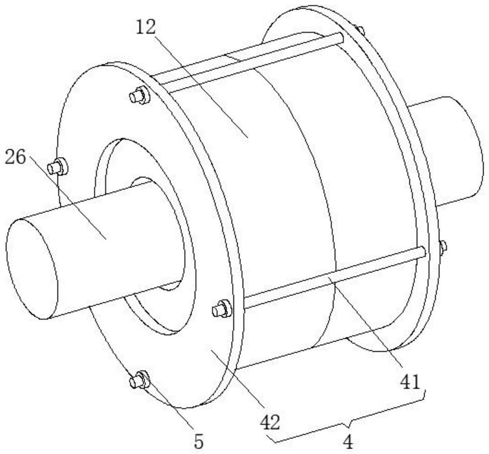
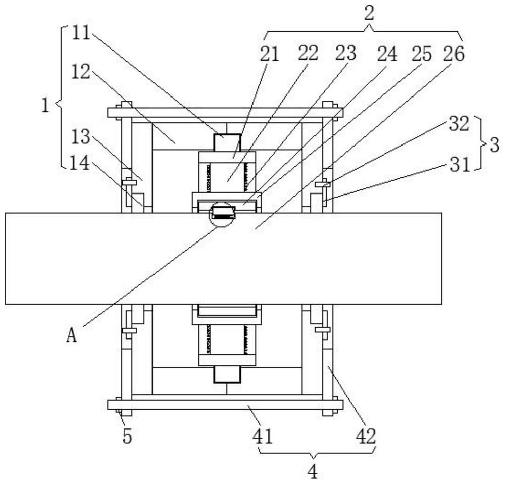
[0025] see Figure 1-3 , the present invention provides a technical solution: a flexible rotor based on an active magnetic suspension bearing, including an auxiliary support mechanism 1 and a magnetic suspension bearing mechanism 2; Tightening ring 12, the ends of the two clamping rings 12 that are far away from each other are provided with support rings 13, and the installation mechanism 4 is installed between the two support rings 13, and the inner sides of ...


PUM


Abstract

The invention discloses a flexible rotor based on an active magnetic suspension bearing. The flexible rotor comprises an auxiliary supporting mechanism and a magnetic suspension bearing mechanism. Theauxiliary supporting mechanism comprises a positioning ring, clamping rings are arranged on the left side and the right side of the positioning ring, supporting rings are arranged at the ends, away from each other, of the two clamping rings, the two supporting rings are installed through a mounting mechanism, auxiliary bearings are arranged on the inner sides of the two supporting rings, and fixing mechanisms are arranged on the outer sides of the two auxiliary bearings. The magnetic suspension bearing mechanism comprises a connecting ring, and core bodies are distributed on the inner side face of the connecting ring in an array mode. An annular electric wire is wound on the side surface of the core body, and the inner end of the core body is provided with a mounting ring; according to the flexible rotor based on the active magnetic suspension bearing, the auxiliary bearings can be fixed, then coaxiality is achieved, high-precision control over the magnetic suspension bearing is achieved, violent friction between a high-speed rotor and the inner ring of the auxiliary bearings can be avoided, and scrapping of a high-speed magnetic suspension motor caused by heat generated by friction is prevented.

Description

technical field [0001] The invention relates to the technical field of flexible rotors, in particular to flexible rotors based on active magnetic suspension bearings. Background technique [0002] Magnetic suspension bearings use magnetic force to suspend the rotor in the air, so that there is no mechanical contact between the rotor and the stator. The principle is that the magnetic induction line is perpendicular to the magnetic floating line, and the shaft core is parallel to the magnetic floating line, so the weight of the rotor is fixed in the running position. On the track, the shaft core with almost no load is used to support the direction of the anti-magnetic floating line to form the entire rotor suspended in the air. On the fixed running track, there is no mechanical contact between the rotor and the stator. However, the existing magnetic bearing stator and auxiliary It is difficult for the bearing to meet the high coaxiality requirements, and then the magnetic gap ...

Claims


Application Information

Patent Timeline
Patent Type & Authority Applications(China)
IPC IPC(8): H02N15/00F16C32/04
CPCF16C32/044F16C32/0444F16C2380/26H02N15/00
Inventor 肖庆朋饶志辉
Owner 江苏联博精密科技股份有限公司
Why Eureka
Try Eureka