Check patentability & draft patents in minutes with Patsnap Eureka AI!

A kind of textile slurry stirring structure

A textile slurry and drum technology, applied in mixer accessories, separation methods, filtration separation, etc., can solve problems such as time-consuming, complicated production process, and complicated weaving process, and achieve the effect of improving the quality of use and stability

Active Publication Date: 2022-04-12
ZHONGYUAN ENGINEERING COLLEGE
View PDF0 Cites 0 Cited by
  • Summary
  • Abstract
  • Description
  • Claims
  • Application Information

AI Technical Summary

Problems solved by technology

[0002] Weaving is to turn textile threads into cloth. The original way of weaving is hand weaving. The weaving process of hand weaving is extremely complicated. There are 72 processes including pulp dyeing, chaotic thread, thread drop, warp thread, thread brushing, heald making, threading, pulling out heald, hanging machine, bolting, weaving, and knitting, all of which are purely handcrafted, purely handmade coarse cloth The product is comfortable, but the production process is complicated and time-consuming; however, with the development of society, since the 1970s, many looms have been put on the market one after another, which can significantly improve the efficiency of weaving; the production process of cloth Generally, through yarn dyeing, yarn sizing, weaving, assembling, rinsing, and drying, yarn dyeing and sizing are usually completed on the sizing-dyeing combined machine, and the mercerizing process can also be completed on the combined machine with the dyeing and sizing process; but the existing technology The textile slurry stirring mechanism used in the sizing machine can only realize the mechanical stirring of the slurry, and cannot filter the impurities in the slurry

Method used


Image

  • A kind of textile slurry stirring structure
  • A kind of textile slurry stirring structure
  • A kind of textile slurry stirring structure

Examples


Embodiment 1

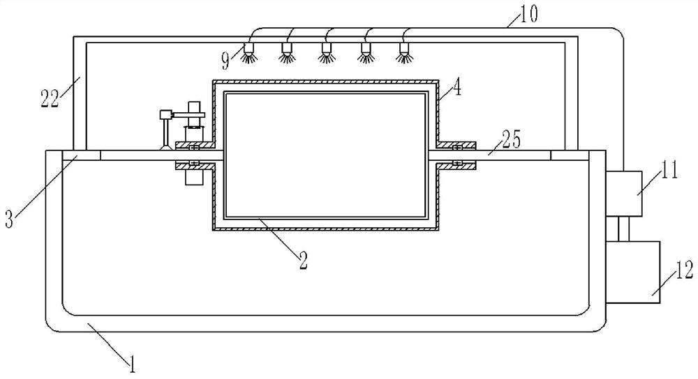
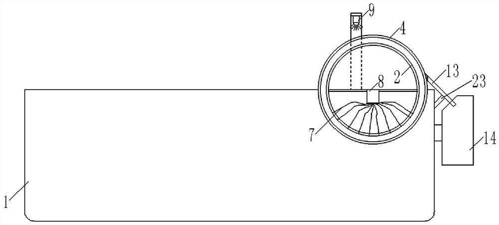
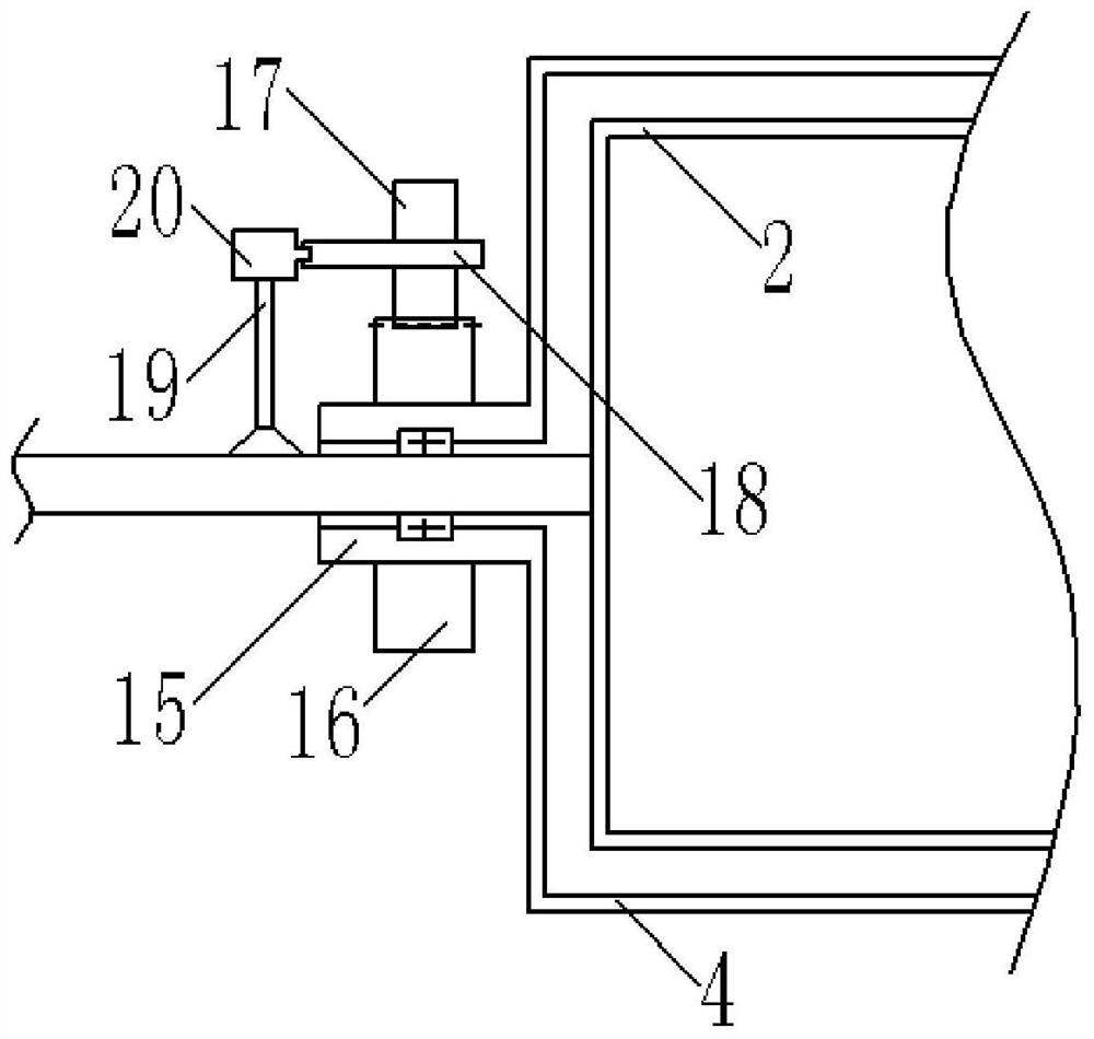
[0034] Embodiment 1: as Figure 1 to Figure 2 As shown, a textile slurry stirring structure includes: a tank body 1, which is used to hold textile slurry; a first drum 2, whose left and right sides are fixed on the tank body 1 by a support frame 3; Rotary cylinder 1 is divided into three fan-shaped areas equidistantly along its axial direction, and the three fan-shaped areas are respectively the suction area located inside the tank body 1, the cleaning area and the filter area located outside the tank body 1; the second Drum 4 is sleeved on the outside of the first drum 2, and its side wall is provided with adsorption components for absorbing impurities such as textile fibers and solid particles in the textile pulp; the suction mechanism is fixed inside the suction area , used to adsorb the impurities inside the textile slurry on the adsorption assembly; the flushing mechanism is located above the cleaning area and fixed on the support frame 3 for washing away the impurities a...


PUM


Abstract

The invention discloses a textile slurry stirring structure, which comprises: a tank body, which is used to contain textile slurry; a first drum, the left and right sides of which are fixed on the tank body by supporting It is divided into three fan-shaped areas in the axial direction, and the three fan-shaped areas are the suction area, the cleaning area, and the filtering area; the second drum is sleeved on the outside of the first drum, and its side wall is equipped with an adsorption component The suction mechanism is fixed inside the suction area; the flushing mechanism is located above the cleaning area and fixed on the support frame; the filter mechanism is located on the side of the filter area and fixed on the support on the frame; the rotating mechanism is fixed on the support frame, and its output end is connected with the second drum; the invention provides a kind of slurry that can be used for textile spraying to be stirred, and the textile fibers in the slurry can be mixed , solid particles and other impurities are filtered out, and the textile slurry stirring structure improves the quality of textile slurry.

Description

technical field [0001] The invention relates to the technical field of textile equipment, in particular to a textile slurry stirring structure. Background technique [0002] Weaving is to turn textile threads into cloth. The original way of weaving is hand weaving. The weaving process of hand weaving is extremely complicated. There are 72 processes including pulp dyeing, chaotic thread, thread drop, warp thread, thread brushing, heald making, threading, pulling out heald, hanging machine, bolting, weaving, and knitting, all of which are purely handcrafted, purely handmade coarse cloth The product is comfortable, but the production process is complicated and time-consuming; however, with the development of society, since the 1970s, many looms have been put on the market one after another, which can significantly improve the efficiency of weaving; the production process of cloth Generally, through yarn dyeing, yarn sizing, weaving, assembling, rinsing, and drying, yarn dyeing...

Claims


Application Information

Patent Timeline
Patent Type & Authority Patents(China)
IPC IPC(8): B01F29/62B01F35/11B01D29/03B01D35/02B01D36/02
CPCB01D35/02B01D29/03B01D36/02B01F29/62B01F35/1453B01F35/123B01F35/187
Inventor 唐予远陈婷李博陈洋
Owner ZHONGYUAN ENGINEERING COLLEGE
Features
  • R&D
  • Intellectual Property
  • Life Sciences
  • Materials
  • Tech Scout
  • Unparalleled Data Quality
  • Higher Quality Content
  • 60% Fewer Hallucinations
Learn More