Ultra-high performance concrete conveying and batching device

An ultra-high performance, concrete technology, applied in clay preparation devices, raw material supply devices for sale, cement mixing devices, etc., can solve problems such as inability to mix concrete, and achieve the effect of ingenious structure, good effect, and easy use and operation.

Pending Publication Date: 2020-11-27
武汉市融筑丽砼园林景观工程有限公司
View PDF12 Cites 3 Cited by
  • Summary
  • Abstract
  • Description
  • Claims
  • Application Information

AI Technical Summary

Problems solved by technology

However, this device cannot achieve efficient m

Method used


Image

  • Ultra-high performance concrete conveying and batching device
  • Ultra-high performance concrete conveying and batching device
  • Ultra-high performance concrete conveying and batching device

Examples


Embodiment 1

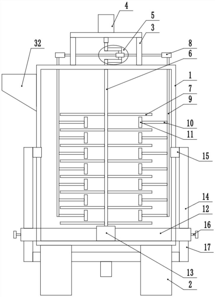
[0022] see Figure 1-4 , a kind of ultra-high-performance concrete conveying batching device, comprises mixing box 1, and the bottom four corners of mixing box 1 are all fixedly connected support leg 2, and the upper side of one side of mixing box 1 is fixedly connected with feeding hopper 32, and described mixing box 1 The top of the box 1 is fixedly connected to the top frame 3, the top of the top frame 3 is fixedly connected to the drive motor 4, the output shaft of the drive motor 4 is fixedly connected to the linkage device 5, and the mixing box 1 is provided with a stirring mechanism and a reciprocating material pushing mechanism. The bottom end of the middle cover 13 is fixedly connected to the middle cover 13, and both sides of the middle cover 13 are fixedly connected to the bottom pipe 12. The end of the bottom pipe 12 away from the middle cover 13 passes through the mixing tank 1, and the top of the end of the bottom pipe 12 away from the middle cover 13 is fixed. C...

Embodiment 2

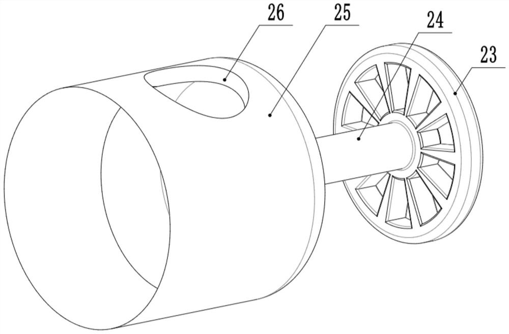
[0029] see Figure 1-4 , the other content of this embodiment is the same as that of Embodiment 1, the difference is that: the feeding switching device 16 includes a second rotating sleeve 25 that is rotatably connected to the inner side of the end of the bottom pipe 12, and the second rotating sleeve 25 is provided with The material delivery port 26 and the end of the second rotating sleeve 25 are fixedly connected to the switching rod 24 , and the switching rod 24 passes through the bottom pipe 12 and is fixedly connected to the hand wheel 23 .

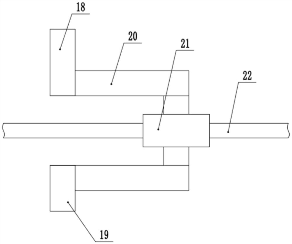
[0030] In the implementation process of the present invention, each raw material of concrete is poured into the mixing box 1 from the feed hopper 32, and then the driving motor 4 is started, and the driving motor 4 drives the U-shaped curved rod 20 to rotate, thereby rotating the rotating shaft 6, and the rotating shaft 6 Drive the stirring paddle 7 to rotate to realize the stirring of the concrete, and at the same time, the U-shape...


PUM


Abstract

The invention discloses an ultra-high performance concrete conveying and batching device, and relates to the technical field of concrete production. The ultra-high performance concrete conveying and batching device comprises a mixing box, the top end of a top frame is fixedly connected with a driving motor, an output shaft of the driving motor is fixedly connected with a linkage device, a stirringmechanism and a reciprocating pushing mechanism are arranged in the mixing box, and the bottom end of the mixing box is fixedly connected with a middle cover; and bottom pipes are fixedly connected to the two sides of the middle cover, and the ends, away from the middle cover, of the bottom pipes penetrate through the mixing box. According to the device, through arranging the linkage device, thestirring mechanism and the reciprocating pushing mechanism can be driven to move synchronously, concrete materials in the mixing box are pushed and stirred, and dual mixing is achieved; through arranging a conveying mechanism and a circulating pipe, concrete deposited at the bottom of the mixing box can be lifted, so that the concrete is more uniform in the mixing box; and switching between mixingand conveying output can be achieved through arranging a conveying switching device, the structural arrangement is ingenious, use and operation are easy, and the mixing and conveying effects on the concrete are good.

Description

technical field [0001] The invention relates to the technical field of concrete production, in particular to an ultra-high performance concrete conveying and batching device. Background technique [0002] Concrete mixing plant is a combined device used to centrally mix concrete, also known as concrete prefabrication field. Due to its high degree of mechanization and automation, its productivity is also high, and it can ensure the quality of concrete and save cement. It is often used in large and medium-sized water conservancy, electric power, bridges and other projects with large concrete engineering volume, long construction period, and concentrated construction sites. With the development of municipal construction, it is of great advantage to use centralized mixing to provide commercial concrete mixing plants, so it has been developed rapidly, and it has created conditions for the promotion of concrete pumping construction and the realization of combined operations of mixi...

Claims


Application Information

Patent Timeline
IPC IPC(8): B28C5/16B28C5/08B28C7/10
CPCB28C5/0806B28C5/0831B28C5/16B28C7/10
Inventor 张丽于志光
Owner 武汉市融筑丽砼园林景观工程有限公司
Why Eureka
Try Eureka