Multi-functional ultrasonic vibration cutting mechanism

An ultrasonic vibration cutting, multi-functional technology, applied in the field of machinery, can solve the problems of inability to meet the requirements of cutting depth, single function, fixed amplitude, etc., and achieve the effect of ingenious structure, multi-function and wide use.

Inactive Publication Date: 2015-01-28
SUZHOU HUACHONG PRECISION MACHINERY
View PDF10 Cites 9 Cited by
  • Summary
  • Abstract
  • Description
  • Claims
  • Application Information

AI Technical Summary

Problems solved by technology

[0004] The cutting trajectory of the existing ultrasonic vibration cutting mechanism is divided into two types: linear type and elliptical type, and these two vibration mechanisms can only cut according to the cor

Method used


Image

  • Multi-functional ultrasonic vibration cutting mechanism
  • Multi-functional ultrasonic vibration cutting mechanism

Examples


Embodiment 1

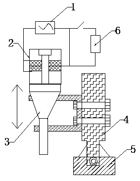
[0020] A multifunctional ultrasonic vibration cutting mechanism, comprising: an ultrasonic signal source 1, a transducer 2, a horn 3, a vibrating tool rest 4 and a cutter 5; the ultrasonic signal source 1 and the transducer 2 pass through The amplifying circuit is connected, the horn 3 is connected with the transducer 2, the vibrating tool rest 4 is fixed on one side of the horn 3 in parallel, and the cutter 5 is installed at the bottom end thereof;

[0021] The amplifying circuit is also connected in parallel with a voltage dividing circuit with a voltage dividing resistor 6 connected in series. The voltage dividing resistor 6 is a digital voltage dividing resistor with an adjustable resistance value, and can also be a plurality of resistors connected in parallel with a fixed resistance value. By adjusting the resistance value on the voltage divider circuit, the voltage value added to the transducer 2 by the amplifying circuit is changed, thereby adjusting the vibration amplit...

Embodiment 2

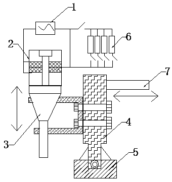
[0023] A multifunctional ultrasonic vibration cutting mechanism, comprising: an ultrasonic signal source 1, a transducer 2, a horn 3, a vibrating tool rest 4, a cutter 5 and a telescopic movement mechanism 7; the ultrasonic signal source 1 and the transducer The amplifiers 2 are connected through an amplifying circuit, the horn 3 is connected to the transducer 2, the vibrating tool holder 4 is fixed on one side of the horn 3 in parallel, and the cutter 5 is installed at the bottom end thereof;

[0024] The amplifying circuit is also connected in parallel with a voltage dividing circuit with a voltage dividing resistor 6 connected in series. The voltage dividing resistor 6 is a digital voltage dividing resistor with an adjustable resistance value, and can also be a plurality of resistors connected in parallel with a fixed resistance value. By adjusting the resistance value on the voltage divider circuit, the voltage value added to the transducer 2 by the amplifying circuit is ch...


PUM


Abstract

The invention discloses a multi-functional ultrasonic vibration cutting mechanism comprising an ultrasonic signal source, a transducer, an amplitude amplifier pole, a vibration tool holder and a tool. The ultrasonic signal source is connected with the transducer through an amplifying circuit; a voltage dividing circuit in series connection with a voltage dividing resistor is in parallel connection on the amplifying circuit; a telescopic movement mechanism is disposed between the vibration tool holder and a connection device of a machine tool provided with the ultrasonic vibration cutting mechanism; the telescopic movement mechanism is controlled by a power plant operating independently; movement direction of the telescopic movement mechanism is perpendicular to that of the amplitude amplifier pole. With the design of the voltage dividing circuit, amplitude magnitude of the tool is adjusted, depth of a cutting tool workpiece is changed, and requirements of different cutting depth are met. With the design of the telescopic movement mechanism operating independently, the tool has two cutting movement performance of linear motion and elliptical motion, and needs of different cutting process are met. Furthermore, the multi-functional ultrasonic vibration cutting mechanism is multi-functional, widely used, applicable to different processing requirements and more practical.

Description

technical field [0001] The invention relates to the field of mechanical technology, in particular to a multifunctional ultrasonic vibration cutting mechanism. Background technique [0002] Diamond knives have the characteristics of high hardness and good thermal conductivity, and can be ground into ultra-precision cutting tools with extremely sharp edges. However, their high chemical affinity with Fe atoms makes graphitization easily occur when cutting ferrous metals, resulting in serious damage. Chemical wear is difficult to apply to ultra-precision cutting of ferrous metals. [0003] Ultrasonic vibration cutting refers to introducing an additional ultrasonic vibration into the original relative motion between the tool and the workpiece, so that the original continuous cutting process becomes regular intermittent cutting. This intermittent cutting can reduce cutting force, cutting temperature, It can significantly reduce tool wear, improve the surface quality of workpieces...

Claims


Application Information

Patent Timeline
IPC IPC(8): B23Q5/02B23Q5/22B06B1/02
CPCB23Q5/02B06B1/02B23Q5/22
Inventor 付冲
Owner SUZHOU HUACHONG PRECISION MACHINERY
Why Eureka
Try Eureka