
Hydraulic auxiliary rock breaking mechanism with direction controllability and cutting method thereof

A hydraulic and rock-breaking technology, which is applied in the field of hydraulic-assisted rock-breaking mechanism and its cutting, can solve the problems of reducing mechanical impact rock-breaking capacity, efficiency, service life and reliability of equipment, low rock-breaking efficiency, and large amount of dust. , to achieve the effects of reducing the difficulty of rock breaking, improving crushing efficiency, and reducing water and abrasive consumption

Active Publication Date: 2020-11-27
CHINA UNIV OF MINING & TECH
View PDF9 Cites 0 Cited by
  • Summary
  • Abstract
  • Description
  • Claims
  • Application Information

AI Technical Summary

Problems solved by technology

However, in the excavation construction of hard rock mass, the existing equipment has problems such as serious wear and shedding of the ball teeth, low rock breaking efficiency and large amount of dust, which greatly reduces the mechanical impact rock breaking ability, efficiency, service life and reliability of the equipment. How to achieve safe and efficient crushing of hard coal rocks has become a key issue and difficulty in the efficient development of deep and complex stratum coal and other ore body resources

Method used


Image

  • Hydraulic auxiliary rock breaking mechanism with direction controllability and cutting method thereof
  • Hydraulic auxiliary rock breaking mechanism with direction controllability and cutting method thereof
  • Hydraulic auxiliary rock breaking mechanism with direction controllability and cutting method thereof

Examples


Embodiment Construction

[0044] The present invention will be described in more detail below with reference to schematic diagrams, wherein preferred embodiments of the present invention are shown, and it should be understood that those skilled in the art can modify the present invention described herein while still achieving the advantageous effects of the present invention. Therefore, the following description should be understood as the broad knowledge of those skilled in the art, but not as a limitation of the present invention.

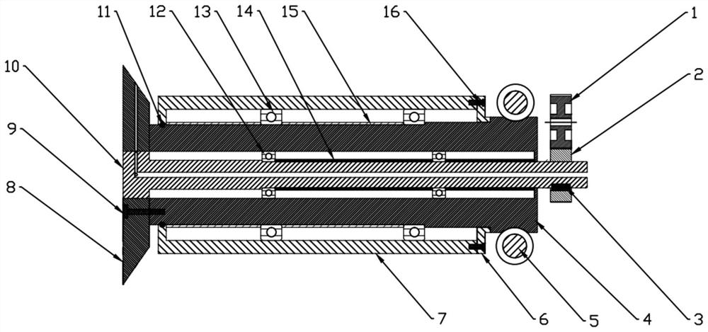
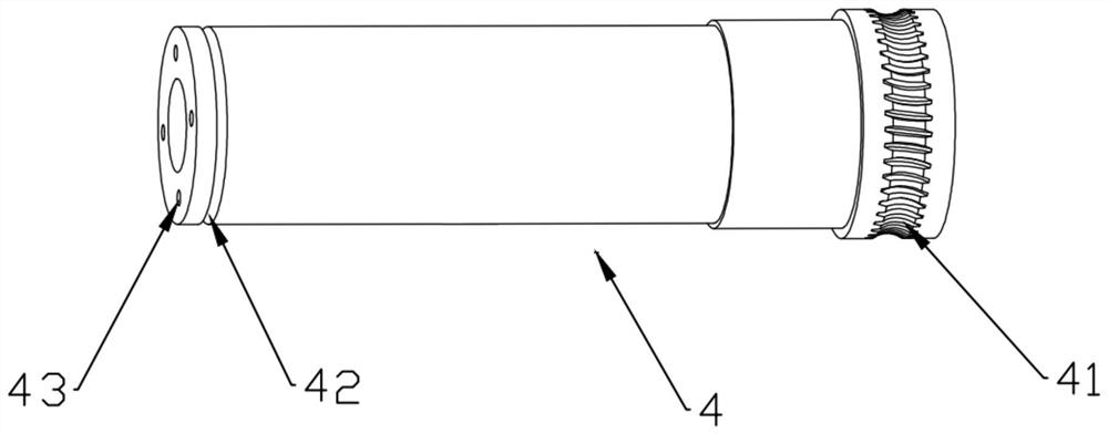
[0045] Such as figure 1As shown, a direction-controllable hydraulic auxiliary rock-breaking mechanism includes a cutting main shaft 4, and a sealing shaft 10 is installed in the cutting main shaft 4; one end of the cutting main shaft 4 is fixed with a hob by fastening screws Ⅰ 9 8. The high-speed abrasive jet generated by the external abrasive jet generator is sprayed into the sealed shaft 10 from the jet inlet of the sealed shaft 10, and the high-speed abrasive jet flows...


PUM


Abstract

The invention provides a hydraulic auxiliary rock breaking mechanism with direction controllability and a cutting method thereof. The mechanism comprises a cutting spindle, wherein a seal shaft is rotatably arranged in the cutting spindle; a hobbing cutter is fixed to one end of the cutting spindle; the cutting spindle and the seal shaft are connected with a motor; a seal shaft axial flow channelis arranged in the seal shaft; a seal shaft radial flow channel and a seal shaft circular arc-shaped groove flow channel are arranged on a cutter close section of the seal shaft; the seal shaft axialflow channel, the seal shaft radial flow channel and the seal shaft circular arc-shaped groove flow channel communicate sequentially; the hobbing cutter is provided with a plurality of hobbing cutterbody jet flow channels penetrating through a cutter body; and a plane on which the hobbing cutter body jet flow channels are located overlaps a plane on which the seal shaft circular arc-shaped grooveflow channel is located. According to the hydraulic auxiliary rock breaking mechanism with direction controllability and the cutting method thereof provided by the invention, the seal shaft, the cutting spindle and the hobbing cutter are matched to provide rotatable abrasive jet flow, the abrasive jet flow pre-slits a part where the hobbing cutter contacting a rock, and then the rotating hobbingcutter extrudes a rock body along the pre-slit crack so as to accomplish the high-efficient vibration cutting and crushing of the rock, so that the crushing efficiency of the rock body is improved.

Description

technical field [0001] The invention belongs to the technical field of rock breaking, and in particular relates to a direction-controllable hydraulic auxiliary rock breaking mechanism and a cutting method thereof. Background technique [0002] The energy industry is the basic industry of the national economy, and it is also a technology-intensive industry. In my country's resource consumption, the consumption of coal resources has always accounted for the main body of the total consumption, and my country's energy is characterized by more coal and less oil, so it will have an irreplaceable position as the main energy source of our country for a long period of time in the future. The rapid development of my country's economy in recent years has led to an increasing demand for coal energy. Nowadays, my country's coal mining has gradually developed to deep and complex strata, which brings difficulties in rock roadway excavation and leads to the imbalance of mining ratio, which...

Claims


Application Information

Patent Timeline
Patent Type & Authority Applications(China)
IPC IPC(8): E21D9/10
CPCE21D9/1006E21D9/1066
Inventor 江红祥朱真才刘送永王欧国沈刚李洪盛
Owner CHINA UNIV OF MINING & TECH
Learn More