
Current measurement method, power supply equipment and power supply chip

A technology of power supply equipment and power chip, which is applied in the direction of measuring electrical variables, measuring current/voltage, measuring devices, etc., can solve the problems of large power consumption of current mirror circuits, reduce power supply efficiency, increase power consumption, etc., and achieve the reduction of power output resistance, improving power supply efficiency, and reducing static power consumption

Active Publication Date: 2020-11-27
GUANGDONG OPPO MOBILE TELECOMM CORP LTD
View PDF11 Cites 3 Cited by
  • Summary
  • Abstract
  • Description
  • Claims
  • Application Information

AI Technical Summary

Problems solved by technology

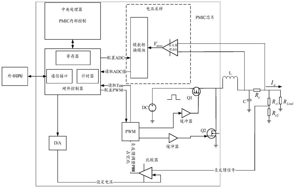
Among them, the specific method of the direct series resistor method is to directly connect the resistor in series at the output end, which will cause a voltage drop on the resistor. When the output current is large, the generated voltage drop is large, and the output voltage will not meet the output requirements; based on this situation , the general practice is to add a negative feedback circuit to further adjust the output voltage to the set value, but this will increase the power consumption
Therefore, the direct series resistance method cannot take into account the size of the output current well, and it will also reduce the power supply efficiency.
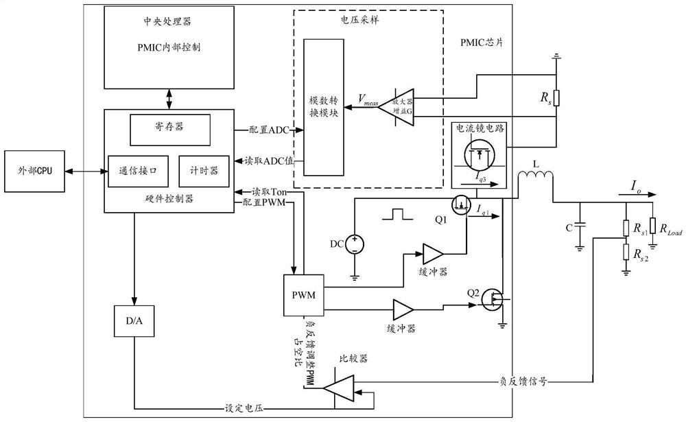
Among them, the current mirror measurement current method is due to the addition of a current mirror circuit. When the ratio of the width to length of the Metal Oxide Semiconductor (MOS) tube is small, the power consumption of the current mirror circuit is too large. When the value is large, the measurement accuracy will decrease
Therefore, the current mirror measurement method is difficult to achieve the optimization of static power consumption

Method used


Image

  • Current measurement method, power supply equipment and power supply chip
  • Current measurement method, power supply equipment and power supply chip
  • Current measurement method, power supply equipment and power supply chip

Examples


Embodiment Construction

[0034] The following will clearly and completely describe the technical solutions in the embodiments of the present application with reference to the accompanying drawings in the embodiments of the present application. Obviously, the described embodiments are only some of the embodiments of the present invention, not all of them. Based on the embodiments of the present invention, all other embodiments obtained by persons of ordinary skill in the art without creative efforts fall within the protection scope of the present invention. In addition, the following embodiments and features in the embodiments can be combined with each other under the condition of no conflict.

[0035] It should be noted that the descriptions such as "first" and "second" involved in the embodiments of the present application are only for the purpose of description, and should not be understood as indicating or implying their relative importance or implicitly indicating the indicated technology number o...


PUM


Abstract

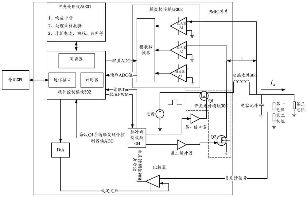
The invention provides a current measurement method, power supply equipment and a power supply chip. The method is applied to a power supply chip. The power supply chip includes an output module and acontrol module, wherein the output module comprises a first switching element and a second switching element; the output module supplies power to a load through an inductance element and a capacitance element which are externally coupled to the power supply chip. The method comprises the steps of providing a switching signal for the first switching element, and acquiring a voltage signal of the inductance element, wherein the voltage signal comprises an input voltage signal and an output voltage signal of the inductance element; obtaining a current ripple characteristic parameter of the inductance element, and determining an inductance value of the inductance element based on the current ripple characteristic parameter; and determining a current signal of the inductance element based on the voltage signal, the inductance value, and the switching signal. Through the embodiment of the invention, the current measurement precision can be improved, and the power supply efficiency is further improved.

Description

technical field [0001] The invention relates to the technical field of electronic circuits, in particular to a current measurement method, a power supply device and a power supply chip. Background technique [0002] With the rapid development of Internet technology, people's demand for terminal equipment is increasing day by day. The energy of terminal equipment comes from batteries, and the supply voltage of batteries is generally a constant value. Terminal equipment is composed of many internal circuits, and the voltage required by different internal circuits may be Different from the supply voltage of the battery. The DC-to-DC (Direct Current convert Direct Current, DC-DC) power supply can convert the battery voltage into a specific voltage that meets internal requirements, and measuring current in a DC-DC circuit has become a hot topic of research. [0003] At present, there are generally two methods for measuring current in a DC-DC circuit: direct series resistance met...

Claims


Application Information

Patent Timeline
Patent Type & Authority Applications(China)
IPC IPC(8): G01R19/00H02M3/00
CPCG01R19/00H02M3/00H02M1/0012H02M1/0083H02M1/0009
Inventor 刘君
Owner GUANGDONG OPPO MOBILE TELECOMM CORP LTD
Learn More