
Simulation test device using returned line to perform cable fault simulation

A fault simulation device, cable fault technology, applied in the direction of measuring devices, measuring electricity, measuring electrical variables, etc., can solve the problems of complex and changeable test site environment, high-voltage cable fault point characteristics and device lack of authenticity, no analysis, etc.

Inactive Publication Date: 2020-11-27
GUANGDONG POWER GRID CORP ZHAOQING POWER SUPPLY BUREAU
View PDF6 Cites 2 Cited by
  • Summary
  • Abstract
  • Description
  • Claims
  • Application Information

AI Technical Summary

Problems solved by technology

The existing fault simulation system does not have enough research on the characteristics of the fault point. It can only be set to high resistance, low resistance, disconnection and other properties, which do not match the characteristics of the actual cable fault point. It is necessary to consider the shape of the cable fault discharge channel and the surrounding medium of the channel. properties, as well as the influence of factors such as breakdown voltage and current under different operating conditions, to establish and analyze the dynamic model of cable fault arc. At present, there is no analysis, research, let alone application in demonstration projects.
[0004] Existing equipment and devices do not conform to the actual situation in terms of demonstration training, and are poorly consistent with the actual line environment and conditions. At the same time, the fault point characteristics and devices of high-voltage cables lack authenticity; general simulation devices can only simulate the wiring and testing process, which is difficult to simulate The discharge waveform of the actual cable and the complex and changeable test site environment

Method used


Image

  • Simulation test device using returned line to perform cable fault simulation
  • Simulation test device using returned line to perform cable fault simulation

Examples


Embodiment Construction

[0021] The accompanying drawings are for illustrative purposes only, and should not be construed as limitations on this patent; in order to better illustrate this embodiment, certain components in the accompanying drawings will be omitted, enlarged or reduced, and do not represent the size of the actual product; for those skilled in the art It is understandable that some well-known structures and descriptions thereof may be omitted in the drawings. The positional relationship described in the drawings is for illustrative purposes only, and should not be construed as a limitation on this patent.

[0022] In the drawings of the embodiments of the present invention, the same or similar symbols correspond to the same or similar components; The orientation or positional relationship indicated by etc. is based on the orientation or positional relationship shown in the drawings, and is only for the convenience of describing the present invention and simplifying the description, rathe...


PUM


Abstract

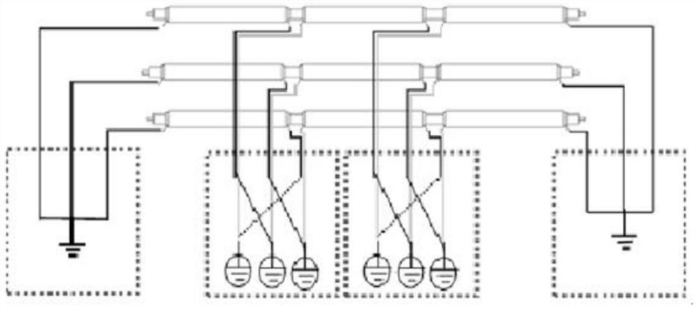
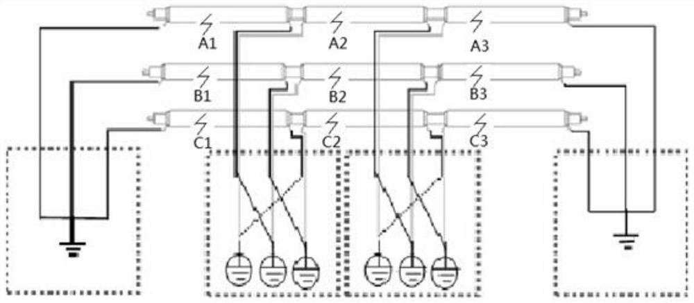
The invention relates to the technical field of cable fault positioning, in particular to a simulation test device using a returned line to perform cable fault simulation. The simulation test device using the returned line to perform cable fault simulation comprises two sections of crossed and interconnected cable lines, a GIS terminal is arranged at one end, and an outdoor terminal is arranged atthe other end and connected with an overhead line. The simulation test device uses the returned line to perform cable fault simulation to carry out design and demonstration application of a simulation test, the consistency with an actual line and an environmental condition is relatively high, and a demonstration training effect is achieved for high-voltage cable fault measurement and seeking; thetest waveform is an actual fault waveform and is more suitable for actual application; and the simulation test device can be repeatedly used, and fatal damage to the cable is avoided.

Description

technical field [0001] The invention relates to the technical field of cable fault location, and more specifically, relates to a simulation test device for simulating cable faults using return lines. Background technique [0002] Existing cable fault location technology and devices cannot meet the requirements of high-voltage cable fault rapid location technology. Although domestic research on cable fault location methods has been carried out for decades, including the bridge method, the traveling wave method has achieved certain results in testing low-resistance faults and breakdown faults, basically meeting the requirements of medium and low voltage faults. Location requirements for cable breakdown faults. For high-voltage and extra-high-voltage cables, long lines must be cross-connected. The traditional impact flashover method for testing three-phase turnkey medium and low-voltage cable faults is used when testing high-voltage cross-connected and transposed cable faults....

Claims


Application Information

Patent Timeline
IPC IPC(8): G01R31/12G01R27/02G01R31/58
CPCG01R31/1272G01R27/025G01R31/58
Inventor 陈敏吴卫堃胡峰孙仝郑耀华陈乃丕袁坤黄育晖朱宇翔
Owner GUANGDONG POWER GRID CORP ZHAOQING POWER SUPPLY BUREAU
Learn More