Photolithography method

A lithography and strip technology, applied in the field of lithography, can solve the problems of cumbersome process steps, high cost, unstable influence of overlay accuracy on lithography resolution, etc., and achieve enhanced resolution and enhanced lithography resolution Effect

Active Publication Date: 2021-07-13
SVG TECH GRP CO LTD +1
View PDF5 Cites 0 Cited by
  • Summary
  • Abstract
  • Description
  • Claims
  • Application Information

AI Technical Summary

Problems solved by technology

However, this method not only has cumbersome process steps and high cost, but also the influence of the overlay accuracy between the two layers of patterns on the lithography resolution is an unstable factor that cannot be ignored

Method used


Image

  • Photolithography method
  • Photolithography method
  • Photolithography method

Examples


Embodiment Construction

[0029] The specific implementation manners of the present invention will be further described in detail below in conjunction with the accompanying drawings and embodiments. The following examples are used to illustrate the present invention, but are not intended to limit the scope of the present invention.

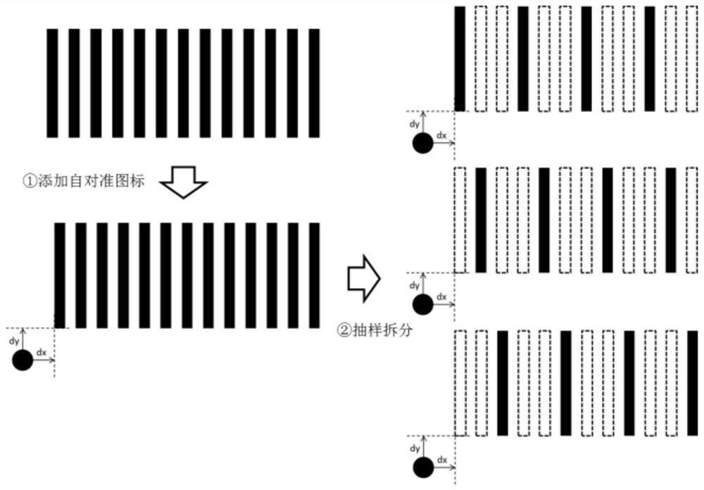
[0030] Please refer to figure 1 , the photolithography method provided in the embodiment of the present invention, the photolithography used for the pattern to be processed includes a photolithography machine with a moving platform, and a preset scanning mode, and the method includes the following steps.

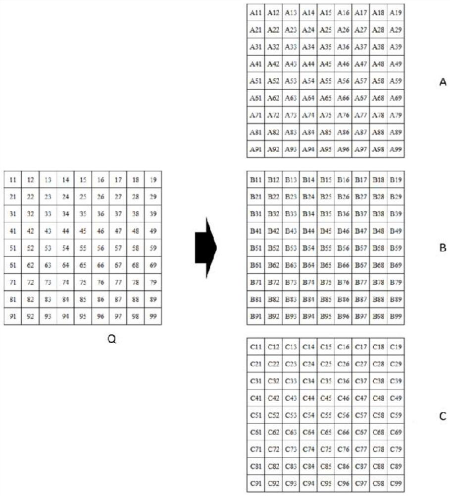
[0031] S1: split the graph to be processed K times to form K sub-graphs;

[0032] Specifically, before splitting, a splitting method and a mark alignment icon are preset. Divide the graph to be processed into K sparse sub-graphs; after splitting, each sub-graph has an alignment icon of the dense graph to be processed. Wherein, the preset splitting method includes regu...


PUM


Abstract

The invention discloses a photolithography method, which is used for photolithography of a pattern to be processed without a mask plate. The method includes the following steps: S1: splitting the pattern to be processed K times to form K sub-patterns; S2: preset split width M, respectively cut the K sub-patterns into n sub-strips according to the preset split width M; The sub-strips are reorganized to form n new strips; S4: photolithography of the new strips, wherein, each time a new strip is photolithographically completed, the width M of one sub-strip is stepped, and another New strip lithography to be processed. By reorganizing the n sub-strips formed by splitting and segmenting the graphics to be processed, the resolution of the sub-strips is enhanced, thereby achieving the effect of enhancing the lithography resolution.

Description

technical field [0001] The invention relates to the technical field of photolithography, in particular to a photolithography method. Background technique [0002] With the rapid development of large-scale integrated circuits, maskless laser direct writing lithography has gradually attracted widespread attention, and is mainly used in precision mask manufacturing, micro-optics, flexible optoelectronic materials, flat panel displays, biosensing and other fields. Most maskless laser direct writing lithography machines on the market are based on spatial light modulators as pattern generators for projection exposure. The process is flexible and saves the high cost of high-precision quartz masks, but it is different from the semiconductor industry. Compared with the projection lithography machine, its lithography resolution is far behind. Therefore, improving the lithography resolution of the maskless laser direct writing lithography machine is still one of the important indicato...

Claims


Application Information

Patent Timeline
Patent Type & Authority Patents(China)
IPC IPC(8): G03F7/20
CPCG03F7/70383G03F7/70425G03F7/70508G03F7/20
Inventor 邵仁锦朱鹏飞张瑾浦东林陈林森
Owner SVG TECH GRP CO LTD
Why Eureka
Try Eureka