A Gradual Adjustable Constant Current Source with High Voltage Output Capability

A technology of high voltage output and constant current source, applied in the field of constant current source, can solve problems such as high cost and no applicable circuit

Active Publication Date: 2022-03-08
茹添俊
View PDF12 Cites 0 Cited by
  • Summary
  • Abstract
  • Description
  • Claims
  • Application Information

AI Technical Summary

Problems solved by technology

As a device, there are special instruments that can be provided, but only a single current source can be provided and the cost is high
As far as we can know, most of them are formed by the conversion of regulated voltage sources, which are basically used below 50-60V. It is difficult to provide a stable current of 2-100mA at more than 200V. There is no lower cost in the existing power electronics technology. Applicable circuit

Method used


Image

  • A Gradual Adjustable Constant Current Source with High Voltage Output Capability
  • A Gradual Adjustable Constant Current Source with High Voltage Output Capability
  • A Gradual Adjustable Constant Current Source with High Voltage Output Capability

Examples


Embodiment 1

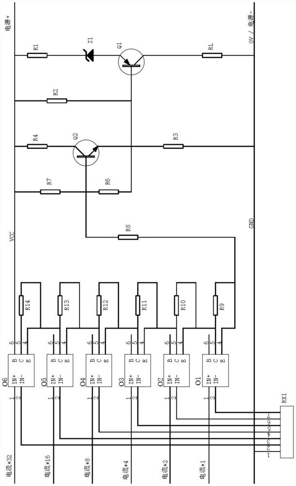
[0025] Example 1, such as figure 1 As shown, a graded adjustable constant current source with high voltage output capability includes optocoupler device exclusion RX1, isolating switch group, constant current source circuit, voltage reference circuit and load RL, and at least one isolating switch group is set An isolating switch, each isolating switch is connected in series with a resistor, and each isolating switch is equipped with a C terminal and an E terminal for adjusting current flow, and the optocoupler device exclusion RX1 is respectively connected with each isolating switch.

[0026] The isolating switch group includes isolating switch O1, isolating switch O2, isolating switch O3, isolating switch O4, isolating switch O5 and isolating switch O6. The output terminal of isolating switch O1 is connected with resistor R9, and the output terminal of isolating switch O2 is connected with resistor R10. The output terminal of the isolating switch O3 is connected to the resist...

Embodiment 2

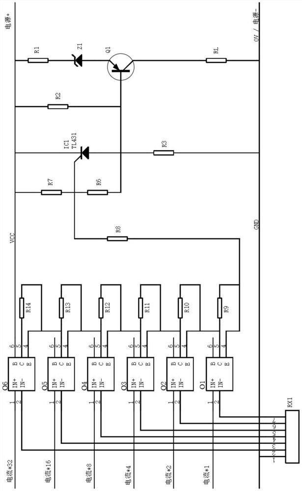
[0036] Embodiment 2, the circuit of the above-mentioned embodiment 1 is a basic circuit, the constant current load adjustment performance is not good enough, and the discreteness of the circuit is also relatively large. In order to improve the circuit performance, the voltage reference can actually use a voltage-stabilizing integrated chip. The circuit diagram is as follows figure 2 shown.

[0037] The difference from Embodiment 1 is that the bipolar transistor Q2 is replaced by a voltage stabilizing integrated circuit IC1. The reference pole of the voltage stabilizing integrated circuit IC1 is connected to the output end of the isolating switch group through the series resistor R8, the anode of the voltage stabilizing integrated circuit IC1 is connected to the negative pole of the power supply GND through the series resistor R3, and the cathode of the voltage stabilizing integrated circuit IC1 is connected to the positive pole of the power supply VCC end connection.

[0038...

Embodiment 3

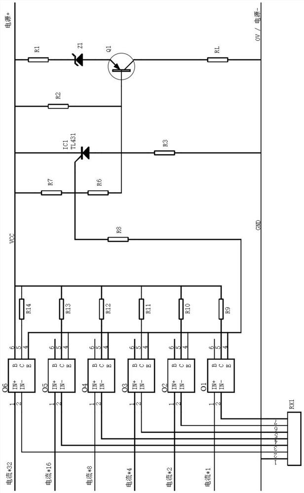
[0041] Example 3, in the above figure 1 with figure 2 In the circuit shown, digital segment adjustment is realized by resistors R9~R14 and isolating switches O1~O6. It belongs to a series circuit. If any resistor is open, although there is resistor R7, it will still cause serious damage to the entire circuit. Impact.

[0042] If higher reliability is required, the resistor network of resistors R9~R14 can also be connected in parallel, the circuit diagram is as follows image 3 As shown, the difference from Embodiment 2 is that the isolating switch O1 is sequentially connected in parallel with the isolating switch O2, the isolating switch O3, the isolating switch O4, the isolating switch O5 and the isolating switch O6. In this embodiment, the working principle and technical effect adopted by the circuit are the same as those in Embodiment 2, and will not be repeated here.


PUM


Abstract

The invention relates to a grade-adjustable constant current source with high-voltage output capability, which includes an optocoupler device exclusion RX1, an isolation switch group, a constant current source circuit, a voltage reference circuit and a load RL, and at least one An isolating switch, each isolating switch is connected in series with a resistor, and each isolating switch is equipped with a C terminal and an E terminal for adjusting the current flow, and the optocoupler device exclusion RX1 is respectively connected with each isolating switch, and the constant current source circuit is composed of Composed of resistor R1, resistor R2, resistor R3, voltage regulator diode Z1 and bipolar transistor Q1, the constant current source circuit is connected in parallel with the voltage reference circuit, and the voltage reference circuit includes resistor R6, resistor R7 and bipolar transistor Q2. In the biasing of the bipolar transistor Q1 in the present invention, a voltage reference circuit with the bipolar transistor Q2 or the voltage stabilizing integrated circuit IC1 as the core is connected in parallel. Within a certain range, different voltage references control the bipolar transistor Q1 as the load RL Provides a set constant current.

Description

technical field [0001] The invention relates to the technical field of power electronics, in particular to a graded adjustable constant current source with high voltage output capability. Background technique [0002] When it is required to obtain multiple independent high-voltage and low-current constant-current sources with adjustable current, especially high-voltage and low-current constant-current sources in the form of pulses, it is found that there is no particularly suitable circuit for use. As a device, there are special instruments that can provide it, but it can only provide a single current source and the cost is high. As far as we can know, most of them are formed by the conversion of regulated voltage sources, which are basically used below 50-60V. It is difficult to provide a stable current of 2-100mA at more than 200V. There is no lower cost in the existing power electronics technology. applicable circuit. [0003] The present invention needs to be able to a...

Claims


Application Information

Patent Timeline
Patent Type & Authority Patents(China)
IPC IPC(8): G05F1/56
CPCG05F1/56
Inventor 茹国斌
Owner 茹添俊
Why Eureka
Try Eureka