
Device and method for measuring polarization dependent loss of polarization maintaining optical fiber device

A polarization-dependent loss, polarization-maintaining fiber technology, applied in the field of optical fiber communication, can solve the influence of power meter noise and measurement error on PDL measurement error, not suitable for polarization-dependent loss measurement of polarization-maintaining fiber components, and light source stability measurement result error, etc. problem, to achieve the effect of accurate polarization state and simple measurement method

Pending Publication Date: 2022-07-01
QUANTUMCTEK
View PDF1 Cites 0 Cited by
  • Summary
  • Abstract
  • Description
  • Claims
  • Application Information

AI Technical Summary

Problems solved by technology

[0007] Although the above-mentioned technical solution can quickly and effectively measure the PDL value in the optical device or system under the condition of single wavelength or multi-wavelength; but the above-mentioned technical solution is not applicable to the measurement of the polarization-dependent loss of the polarization-maintaining optical fiber device
[0008] If the four-state measurement method is used, it is necessary to generate four polarization states to measure the PDL of the device, but it needs to measure 8 power values ​​to calculate the PDL. The noise and measurement error of the power meter will greatly affect the measurement error of the PDL.
Secondly, due to the need to measure the power without and through the device under test successively, the stability of the light source will have a great error effect on the measurement results

Method used


Image

  • Device and method for measuring polarization dependent loss of polarization maintaining optical fiber device
  • Device and method for measuring polarization dependent loss of polarization maintaining optical fiber device
  • Device and method for measuring polarization dependent loss of polarization maintaining optical fiber device

Examples


Embodiment 1

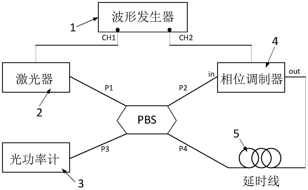
[0035] like figure 1 As shown, the device for measuring polarization-dependent loss of a polarization-maintaining optical fiber device in this embodiment includes a waveform generator 1, a laser 2, an optical power meter 3, a phase modulator 4, and a delay line 5. The device under test in this embodiment For the four-port polarizing beam splitter PBS.

[0036] The four-port polarization beam splitter has four pigtails P1, P2, P3, and P4, all of which are polarization-maintaining fibers. The pigtail P1 is connected to the laser 2, the pigtail P2 is connected to the in port of the phase modulator 4, and the pigtail P3 is connected to the optical power meter. 3. For measuring the optical power, the pigtail P4 is connected to one end of the delay line 5; the laser 2 is connected to the CH1 port of the waveform generator 1; the phase modulator 4 is connected to the CH2 port of the waveform generator 1, and the out of the phase modulator 4 The port is connected to the other end of ...

Embodiment 2

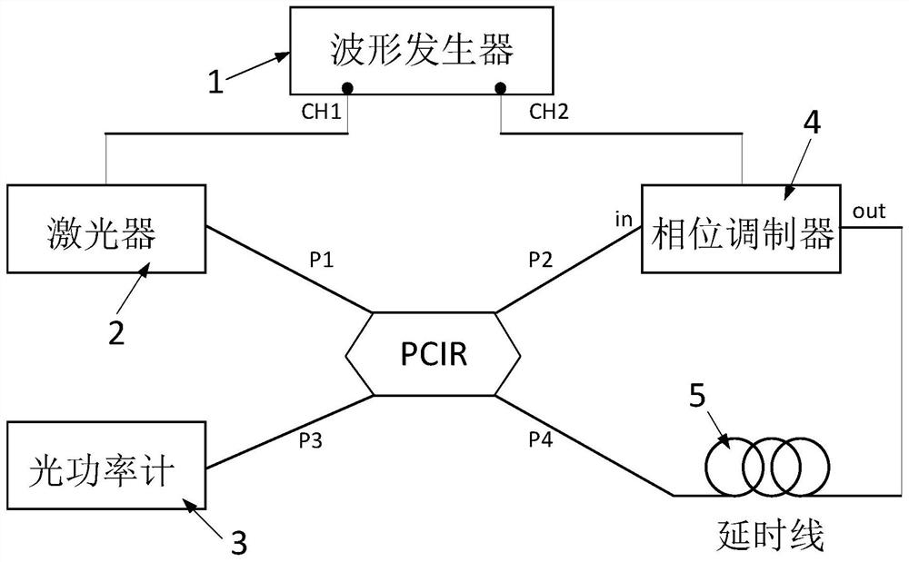
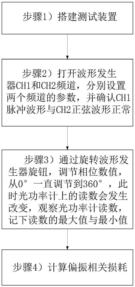
[0047] like figure 2 As shown, what is different from the first embodiment is that the device under test in this embodiment is a circular polarizing beam splitter (PCIR), and this embodiment replaces the PBS in the first embodiment with a circular polarizing beam splitter (PCIR) , the light emitted by laser 2 enters from the pigtail P1 of the circular polarization beam splitter, and is divided into two polarized beams after passing through the PBS in the PCIR. Superposition at PCIR to form Sagnac loops. like image 3 As shown, the measurement method of this embodiment is the same as the measurement method of the first embodiment.


PUM


Abstract

The invention discloses a device and a method for measuring the polarization dependent loss of a polarization-maintaining optical fiber device, belongs to the technical field of optical fiber communication, and solves the technical problem of how to accurately measure the polarization dependent loss of a device adopting a polarization-maintaining optical fiber. Through the established measuring device, the value of the polarization dependent loss (PDL) of the optical device of which the input end is the polarization maintaining optical fiber is measured, the calculation of the PDL only needs to record the maximum value and the minimum value in the optical power meter, the difference between the two values is solved, and the measuring method is simple; the waveform generator sends a signal to the phase modulator, and changes the voltage value so as to change the polarization state of light, which is more accurate than adjusting the polarization rotator to change the polarization state of light.

Description

technical field [0001] The invention belongs to the technical field of optical fiber communication, and relates to a measurement device and method for polarization-dependent loss of a polarization-maintaining optical fiber device. Background technique [0002] Polarization Dependent Loss (PDL) is the maximum transmission difference of an optical device or system in all polarization states, and it is the ratio of the maximum transmission to the minimum transmission of an optical device in all polarization states. Polarization-dependent loss has now become a standard metric to characterize passive optical devices. There are currently two main PDL measurement methods: the polarization scanning method and the stationary state method. The polarization scanning method is a relative measurement method. The actual measurement value reflects the deviation of the optical power with the change of the polarization state of the incident light. The difference between the maximum value an...

Claims


Application Information

Patent Timeline
Patent Type & Authority Applications(China)
IPC IPC(8): G01M11/00G01M11/02
CPCG01M11/337G01M11/333G01M11/0207
Inventor 唐世彪郑伯然杜先常吕海燕
Owner QUANTUMCTEK
Learn More