
A circuit and method for eliminating output DC offset

A DC offset and circuit technology, applied in DC-coupled DC amplifiers, electrical components, transmission systems, etc., can solve the problems of output DC offset, increase cost, and the pre-stage circuit cannot generate differential signals, and achieve real-time adjustment and flexible application. Wide, offset voltage cancellation effect

Active Publication Date: 2019-04-19
CHENGDU GANIDE TECH
View PDF4 Cites 0 Cited by
  • Summary
  • Abstract
  • Description
  • Claims
  • Application Information

AI Technical Summary

Problems solved by technology

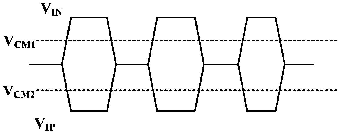
[0003] However, sometimes the front-end circuit cannot generate differential signals with the same common mode point, but there will be output DC offset, such as the output waveform of the differential transimpedance amplifier, such as figure 2 As shown, high-frequency applications often use AC coupling to solve the above problems, that is, there are two differential signals with DC offsets. After passing through the coupling capacitor and adding the bias circuit of the subsequent stage, a differential signal with a common-mode point biased at one potential is formed. Signal
[0004] However, in low-frequency applications, a very large coupling capacitor is required to achieve a better DC blocking effect, which is impossible to integrate on-chip. If an off-chip capacitor is used, monolithic integration cannot be achieved, and at the same time, the cost is increased.

Method used


Image

  • A circuit and method for eliminating output DC offset
  • A circuit and method for eliminating output DC offset
  • A circuit and method for eliminating output DC offset

Examples


Embodiment Construction

[0040] The principles and features of the present invention are described below in conjunction with the accompanying drawings, and the examples given are only used to explain the present invention, and are not intended to limit the scope of the present invention.

[0041] The invention aims to provide a method for eliminating the output DC offset applied at a lower frequency, and provides circuit realization.

[0042] like image 3 As shown, a circuit for eliminating output DC offset, including a preamplifier circuit, an amplitude detection circuit, a wave detection circuit, an adjustment current generation circuit and a DC correction circuit connected in sequence; the preamplifier circuit is connected to the DC correction circuit;

[0043] The preamplifier circuit is used to output the differential signal with offset and transmit it to the amplitude detection circuit and the DC correction circuit;

[0044] The amplitude detection circuit is used to detect the maximum swing of ...


PUM


Abstract

The invention relates to a circuit and method used for eliminating the output direct-current offset. The circuit comprises a pre-stage amplification circuit, an amplitude detection circuit, a detector circuit, an adjusting current generating circuit and a direct-current correction circuit, which are successively connected. The pre-stage amplification circuit is connected with the direct-current correction circuit. According to the invention, by properly setting resistance values of related resistors, the offset voltage of differential signals in different offset degrees can be eliminated. The amplitude of an original signal is firstly detected, then, the adjusting value is calculated according to the amplitude of the original signal, and the original signal is adjusted by use of the calculated adjusting value. Thus, real-time adjustment can be performed when the amplitude of the original signal is changed, so the circuit and the method are flexibly and widely applied.

Description

technical field [0001] The invention relates to integrated circuit design, in particular to a circuit and method for eliminating output direct current offset. Background technique [0002] In integrated circuit design, for amplifier circuits with differential input, it is generally required that the common-mode point of the two differential input signals be biased at a potential V CM ,like figure 1 As shown, this allows the amplifier circuit to be biased in normal operation. [0003] However, sometimes the front-end circuit cannot generate differential signals with the same common mode point, but there will be output DC offset, such as the output waveform of the differential transimpedance amplifier, such as figure 2 As shown, high-frequency applications often use AC coupling to solve the above problems, that is, there are two differential signals with DC offsets. After passing through the coupling capacitor and adding the bias circuit of the subsequent stage, a different...

Claims


Application Information

Patent Timeline
Patent Type & Authority Patents(China)
IPC IPC(8): H04B1/30H03F3/45
CPCH03F3/45H03F3/45968H04B1/30H04B2001/305
Inventor 刘浩苏黎郑微任军伍莲洪
Owner CHENGDU GANIDE TECH
Learn More