Board-level radio frequency signal test system, method and device without radio frequency test socket

A radio frequency test socket and radio frequency signal technology, which is applied in transmitter monitoring, receiver monitoring, etc., can solve the problems of limited motherboard design space, failure to improve the quality of radio frequency signal transmission and reception on wireless product boards, and increase the material cost of wireless products. Rigorous test, fast RF signal test, ingenious structure effect

Active Publication Date: 2021-04-20
深圳合一测试科技有限公司
View PDF7 Cites 0 Cited by
  • Summary
  • Abstract
  • Description
  • Claims
  • Application Information

AI Technical Summary

Problems solved by technology

At present, more RF test sockets are added to the motherboard of wireless products through the design and development stage; the number of RF test sockets on the motherboard of wireless products in the 2~4G era is calculated in single digits, and this number will rise to 10 in the 5G era The above is to meet the needs of traditional board-level RF testing; for wireless products with increasingly complex designs, higher performance, and better user experience, the design space on the motherboard is very limited, and more than 10 RF test sockets It is only to meet the test requirements of ensuring the quality of radio frequency signals before the launch of wireless products, and does not improve the quality of sending and receiving radio frequency signals on the board of wireless products after listing
Instead, it is necessary to reserve more than 10 board-level RF test socket installation spaces on the limited motherboard space in the wireless product design stage, and increase the material cost of wireless products

Method used


Image

  • Board-level radio frequency signal test system, method and device without radio frequency test socket
  • Board-level radio frequency signal test system, method and device without radio frequency test socket
  • Board-level radio frequency signal test system, method and device without radio frequency test socket

Examples


Embodiment Construction

[0034] In order to express the present invention more clearly, the present invention will be further described below in conjunction with the accompanying drawings.

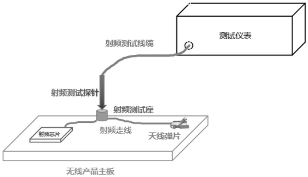
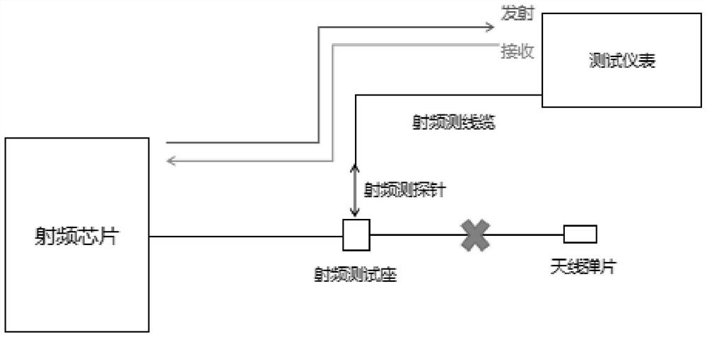
[0035] The function of the RF test socket is to form an electrical connection by mechanically snapping the RF probe and the RF test socket when performing board-level RF performance tests on wireless products; then when the RF signal sent or received by the RF chip on the motherboard of the wireless product , the signal will be transmitted to the test instrument through the RF test socket and the RF probe to test the RF signal; after the test is completed, pull out the probe; Antenna shrapnel, the radio frequency signal is sent by the antenna shrapnel to achieve the purpose of wireless communication; see figure 2 , Therefore, the function of the RF test socket is only to test the test requirements of the RF signal quality in the RF circuit, and does not contribute to the improvement of the RF signal quality itsel...


PUM


Abstract

The board-level radio frequency signal testing system, method and device proposed by the present invention without radio frequency test socket are used to test radio frequency signals of radio frequency circuits; including radio frequency test probes, tuning modules and test instrument modules, one end of radio frequency test probes and radio frequency The antenna shrapnel of the circuit is connected, and the other end is connected to the tuning module; the tuning module is connected to the test instrument module, and the tuning module adjusts the matching impedance according to the return loss; the matching impedance matches the impedance of the radio frequency circuit; The shrapnel of the antenna is electrically connected, and then the size of the matching impedance is adjusted through the tuning module, and the size of the return loss can be used to judge whether the matching impedance is matched in place until the matching impedance matches the impedance in the radio frequency circuit, so that it can be directly passed through the antenna. The purpose of the shrapnel for RF signal testing; the test results are rigorous and the structure is ingenious; the design space and production cost of the RF test socket in the RF circuit are saved.

Description

technical field [0001] The invention relates to the technical field of radio frequency signal testing, in particular to a board-level radio frequency signal testing system, method and device without a radio frequency test seat. Background technique [0002] In recent years, with the continuous development of communication technology, the popularity of wireless products has become higher and higher, and the number of wireless products produced in the world is also increasing every year, and people's production and life are becoming more and more convenient. Wireless products (represented by mobile phones) mainly refer to the communication frequency operating at 300kHz~300GHz, and the communication signals in this frequency range are also called radio frequency signals. In order to ensure the quality of the RF signal on the motherboard of wireless products and meet a series of the most basic wireless communication requirements of wireless products, it is usually necessary to p...

Claims


Application Information

Patent Timeline
Patent Type & Authority Patents(China)
IPC IPC(8): H04B17/15H04B17/29
CPCH04B17/15H04B17/29
Inventor 刘好唐锡辉左达恒
Owner 深圳合一测试科技有限公司
Why Eureka
Try Eureka