
Combustion heat supply mechanism in reforming hydrogen production device

A reforming hydrogen production device, combustion heating technology, applied in the fields of hydrogen, inorganic chemistry, hydrogen/synthesis gas production, etc., can solve the problem of poor gas and air preheating effect, limited space in the reforming reaction zone, and poor heating uniformity and other problems, to achieve the effect of increasing space, stable ion current detection, and reducing heat load

Active Publication Date: 2020-12-01
江苏铧德氢能源科技有限公司
View PDF11 Cites 4 Cited by
  • Summary
  • Abstract
  • Description
  • Claims
  • Application Information

AI Technical Summary

Problems solved by technology

[0003] The disadvantages of the above-mentioned small-scale reforming hydrogen production device are: 1. The reforming reaction zone in the reaction chamber is poorly heated, which affects the reaction efficiency
2. The temperature inside the combustion cylinder and the bottom of the combustion cylinder is high, so the interlayer between the side walls above the bottom of the inner and outer cylinders can only be used as the reforming reaction zone, and the space of the reforming reaction zone is limited.
3. The preheating effect of gas and air is poor, and the combustion efficiency is relatively low

Method used


Image

  • Combustion heat supply mechanism in reforming hydrogen production device
  • Combustion heat supply mechanism in reforming hydrogen production device
  • Combustion heat supply mechanism in reforming hydrogen production device

Examples


Embodiment Construction

[0022] The present invention will be further described in detail below in conjunction with the accompanying drawings and preferred embodiments.

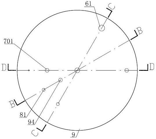
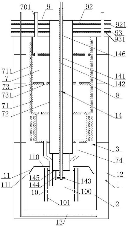
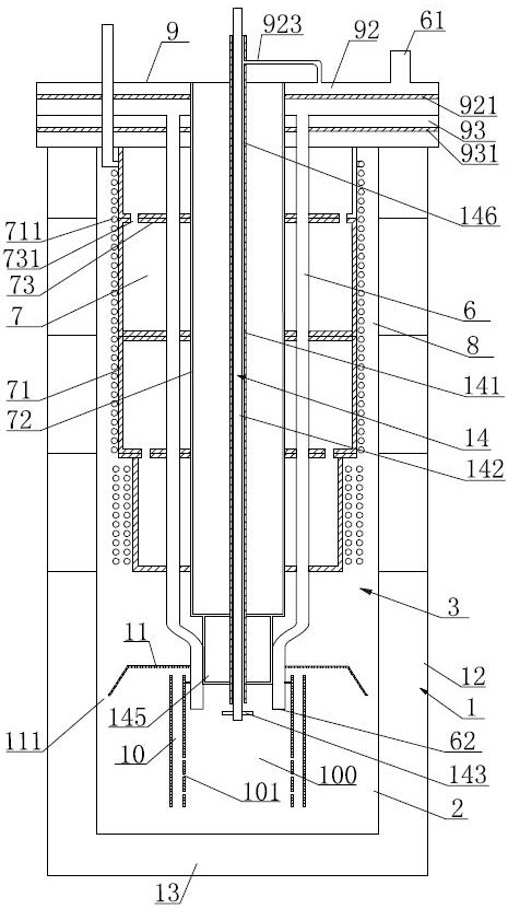
[0023] Such as figure 1 , figure 2 , image 3 , Figure 4 , Figure 5 , Figure 6 As shown, the combustion heat supply mechanism in the reforming hydrogen production device includes: a cavity 3 formed around the reaction chamber 1, the top of the cavity 3 is closed, and the bottom of the cavity 3 is the furnace 2. In order to increase the heat exchange area, To improve the heat exchange effect, the inner wall of the furnace 2 is serrated, such as Figure 6 shown. The cavity above the furnace 2 is provided with a burner 14 , a gas passage, an air passage 7 , and a waste gas discharge passage 8 . The furnace 2 is provided with several return pipes 10, there is a gap between the lower end of the return pipe 10 and the bottom of the furnace 2, the return pipes 10 are arranged at intervals in the circumferential direction, and the...


PUM


Abstract

The invention discloses a combustion heat supply mechanism in a reforming hydrogen production device. The combustion heat supply mechanism comprises a cavity formed by surrounding a reaction chamber,the top of the cavity is closed, and a hearth is arranged at the lower end part in the cavity; a combustor, a gas channel, an air channel and a waste gas exhaust channel are arranged in the cavity above the hearth; a plurality of return pipes are arranged in the hearth; the return pipes surround to form a combustion area; the top of the combustion area is closed, and outlets of the air channel andthe gas channel are positioned in the combustion area; the ignition device of the combustor is positioned at the upper end part in the combustion area; and a plurality of backflow holes are formed inthe pipe wall, located on one side of the combustion area, of each return pipe, a baffle is arranged above the return pipes, gaps are reserved between the baffle and the inner wall of the hearth andbetween the baffle and the upper end openings of the return pipes, and the gap between the baffle and the inner wall of the hearth is communicated with the waste gas exhaust channel. The combustion heat supply mechanism has the advantages that: the whole hearth is uniformly heated, so that the reforming reaction area of the reaction chamber is uniformly heated, and the reaction efficiency is improved.

Description

technical field [0001] The invention relates to the technical field of reforming hydrogen production equipment, in particular to a small reforming hydrogen production device. Background technique [0002] In order to widely promote hydrogen energy, it is imperative to miniaturize the reforming hydrogen production unit. At present, the structure of the small-scale reforming hydrogen production device mainly includes: an annular reaction chamber formed by the inner and outer cylinders, the top of the reaction chamber is closed, and the reaction chamber is sequentially divided into reforming reaction areas for placing reforming reaction catalysts, placing The low variable reaction zone of the water vapor transfer reaction catalyst, the selective methanation reaction zone where the selective methanation reaction catalyst is placed; the cavity formed around the reaction chamber, and the combustion heat supply mechanism is set in the cavity, and the combustion heat supply mechanis...

Claims


Application Information

Patent Timeline
IPC IPC(8): B01J19/00C01B3/38
CPCB01J19/0013B01J2219/00076B01J2219/00157C01B3/38C01B2203/0244C01B2203/0811
Inventor 蔡信吕青青
Owner 江苏铧德氢能源科技有限公司
Features
  • Generate Ideas
  • Intellectual Property
  • Life Sciences
  • Materials
  • Tech Scout
  • Unparalleled Data Quality
  • Higher Quality Content
  • 60% Fewer Hallucinations
Learn More