
Follow-up bending machine clamp

A bending machine and follow-up technology, which is applied in mechanical equipment, manufacturing tools, vibration suppression adjustment, etc., can solve the problems of bending machine position and angle error, inability to realize automation, and lack of real-time motion parameter manipulator linkage function, etc.

Pending Publication Date: 2020-12-01
CHINA HUALU PANASONIC AVC NETWORKS
View PDF0 Cites 1 Cited by
  • Summary
  • Abstract
  • Description
  • Claims
  • Application Information

AI Technical Summary

Problems solved by technology

[0005] However, many bending machine CNC systems in factories do not have real-time motion parameters and manipulator linkage functions. After programming with manipulators, position and angle errors will occur with the bending machine.
It is impossible to achieve automatic and efficient bending

Method used


Image

  • Follow-up bending machine clamp
  • Follow-up bending machine clamp

Examples


Embodiment Construction

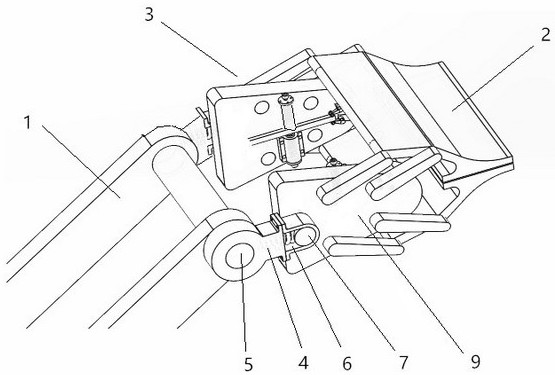
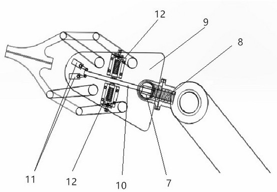
[0013] The specific implementation manner of the present invention will be described below with reference to the accompanying drawings. Such as figure 1 , figure 2 Shown: a follow-up bending machine clamp, which is composed of a mechanical arm 1, a clamp body 2 and a connecting mechanism 3 between them,

[0014] The connecting mechanism 3 includes two symmetrically distributed first connecting parts 4, the first connecting parts 4 are hinged to the end of the mechanical arm 1 through the first rotating shaft 5, and there are long lengths on the first connecting parts 4. Slot 6, the second rotating shaft 7 is slidably connected in the long slot 6, and a spring 8 is also provided in the long slot 6 between its inner wall and the second rotating shaft 7, and a distance is also provided in the long slot 6 sensor, the first connecting piece 4 is also slidably connected with the second connecting piece 9 through a chute slider mechanism, and the first connecting piece 4 and the s...


PUM


Abstract

The invention discloses a follow-up type bending machine clamp. The follow-up type bending machine clamp is characterized in that the clamp is composed of mechanical arms, a clamp body and a connecting mechanism between the mechanical arms and the clamp body; the connecting mechanism comprises two first connecting pieces which are symmetrically distributed; the first connecting pieces are hinged with the end parts of the mechanical arms through first rotating shafts; elongated slots are formed in the first connecting pieces; second rotating shafts are slidably connected into the elongated slots; meanwhile, springs abutting between the inner walls of the second rotating shafts are further arranged in the elongated slots; distance sensors are further arranged in the elongated slots; the second rotating shafts are movably connected to second connecting pieces in a penetrating mode; angle swing rods are connected to the free ends of the second rotating shafts, and angle sensors matched with the free ends of the angle swing rods are arranged on the second connecting pieces; and meanwhile, two buffer springs which are distributed with the angle swing rods as the center in an axial symmetry mode are further arranged on the second connecting pieces, and the tail ends of the second connecting pieces are connected with the clamp body.

Description

technical field [0001] The invention relates to a fixture, in particular to a follower type bending machine fixture. Background technique [0002] In sheet metal processing, the bending machine is a commonly used large-scale machine. At this stage, traditional processing methods are commonly used in factories: the workers work in coordination with their hands and feet, the feet control the falling speed of the tool, and their hands follow the movement trajectory of the workpiece. [0003] This way of working requires a high level of work experience for the workers. If the hands of the worker cannot fit the workpiece closely, the steel plate will be deformed during the bending process due to the weight of the steel plate itself, resulting in poor processing accuracy of the steel plate, or even broken parts. When batch precision bending is required, the precision and consistency of each workpiece are required to be higher. Traditional working methods are difficult to meet th...

Claims


Application Information

Patent Timeline
IPC IPC(8): B21D5/00B21D43/00B21C51/00F16F15/067
CPCB21C51/00B21D5/002F16F15/067
Inventor 宋健赵艳龙周瑀杭吕义伟邹剑秋于世洋
Owner CHINA HUALU PANASONIC AVC NETWORKS
Learn More