
Bending device for bending machine

A bending device and bending machine technology, applied in the direction of feeding device, positioning device, storage device, etc., can solve the problems of difficult precise control of bending angle, driving inertia error, etc., and achieve simple structure and eliminate driving inertia error Effect

Pending Publication Date: 2020-12-01
QINGDAO WUXIAO GRP
View PDF0 Cites 0 Cited by
  • Summary
  • Abstract
  • Description
  • Claims
  • Application Information

AI Technical Summary

Problems solved by technology

[0003] The technical problem to be solved by the present invention is to overcome the shortcomings of the push-top bending device used in the existing bending machine that it is difficult to accurately control the bending angle and the error caused by the driving inertia, and to provide a bending angle that can be accurately controlled. A bending device for a bending machine that eliminates drive inertia errors

Method used


Image

  • Bending device for bending machine
  • Bending device for bending machine
  • Bending device for bending machine

Examples


Embodiment approach 2

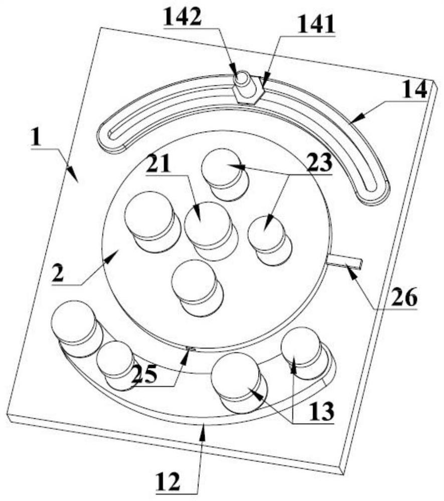
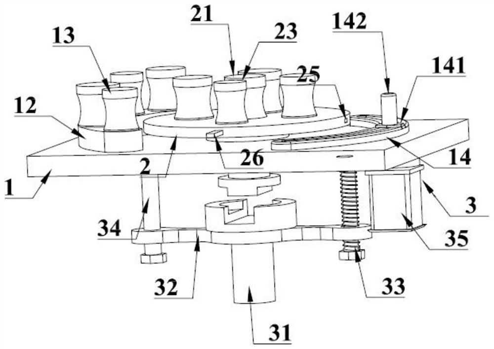
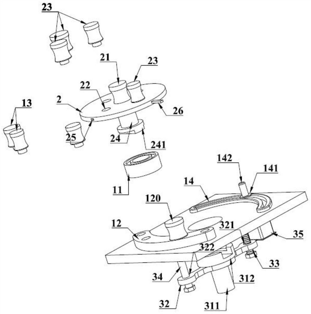
[0028] like Figure 4 As shown, the lower surface of the fixture table 1 is provided with a protective cover 15, and the protective cover is provided with a mounting bearing and a transmission belt. The screw rod 33 is installed on the connecting bearing and passes through the protective cover 15. The stepping motor 35 is installed on the protective cover 15, the output shaft of the stepping motor 35 penetrates the protective cover 15, and is connected with the described screw mandrel 33 by the transmission belt. Other components and structures are as described in Embodiment 1, omitted.

[0029] like Figures 5 to 6 As shown, in specific use, connect the motor shaft sleeve 311 on the bending device with the main motor, and select the appropriate torsion shaft 23 according to the workpiece during operation, and place the part of the workpiece to be bent between the base shaft 21 and the torsion shaft 23 Then insert the retaining shaft 13 to fix it, adjust the position of the ...


PUM


Abstract

The invention relates to a bending device for a bending machine, belongs to the technical field of machining mechanical devices, and particularly discloses a bending device for a bending machine for accurately controlling the bending angle and eliminating the drive inertia errors. The bending device comprises a jig table, a torsion disc and a transmission mechanism, and a base shaft, a torsion shaft seat hole, a torsion shaft and an upper half coupling shaft are arranged on the torsion disc; and the transmission mechanism comprises a lower half coupling shaft, a sliding frame, a lead screw, aguide rod and a stepping motor. A hole is formed in the center of the jig table, a large disc bearing is fixedly installed in the hole, the torsion disc is rotationally connected to the upper portionof the jig table through the large disc bearing, the lead screw is rotationally connected to the lower portion of the jig table through a bearing, the guide rod is welded to the lower portion of the jig table, and the upper half coupling shaft penetrates through the hole in the center of the jig table to be movably connected with the lower half coupling shaft.

Description

technical field [0001] The invention relates to the technical field of profile processing mechanical devices, in particular to a bending device for a bending machine. Background technique [0002] Most of the bending mechanisms used in existing bending machines are composed of fixing parts and ejecting parts, and hydraulic motors are used as power to realize profile bending through the parts to be bent of the ejecting parts. It is difficult to accurately control the bending angle in the above-mentioned structural form that achieves bending through the stroke of the ejector, and after the shutdown, due to the deceleration of the motor or the pressure relief of the hydraulic oil, it is a gradual disappearance process, and the inertial driving force still exists during this process, thereby resulting in the bending angle error. Contents of the invention [0003] The technical problem to be solved by the present invention is to overcome the shortcomings of the push-top bendin...

Claims


Application Information

Patent Timeline
Patent Type & Authority Applications(China)
IPC IPC(8): B21D7/08B21D7/16B21D43/00B21C51/00
CPCB21D7/08B21D7/16B21D43/003B21C51/00
Inventor 康金霞周晓艳
Owner QINGDAO WUXIAO GRP
Learn More