Welding equipment facilitating welding angle adjustment

A welding equipment and welding angle technology, which is applied to welding accessories, welding rod characteristics, cleaning torches, etc., can solve the problems of inconvenient welding angle adjustment, inconvenient welding, and inability to remove welding slag. Easy to collect effects

Inactive Publication Date: 2020-12-01
江先庆
View PDF0 Cites 6 Cited by
  • Summary
  • Abstract
  • Description
  • Claims
  • Application Information

AI Technical Summary

Problems solved by technology

[0004] The purpose of the present invention is to solve the problem that the welding device in the prior art is inconvenient to adjust the welding angle, making it inconvenient to perform comprehensive welding on the periphery of the workpiece, and the welding slag cannot be removed at the same time after welding, resulting in The quality of welding cannot be checked in time, and it is not convenient to collect the welding slag that falls by itself, which leads to the shortcomings of welding slag accumulation on the processing table and is difficult to clean up. A welding equipment that is easy to adjust the welding angle is proposed

Method used


Image

  • Welding equipment facilitating welding angle adjustment
  • Welding equipment facilitating welding angle adjustment
  • Welding equipment facilitating welding angle adjustment

Examples


Embodiment 1

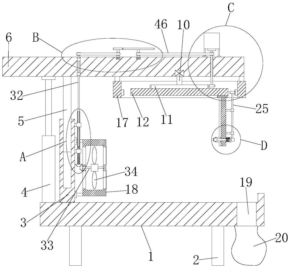
[0030] refer to Figure 1-6 , a kind of welding equipment that is convenient for adjusting the welding angle, including a base 1, the bottom of the base 1 is fixedly connected with a foot 2, the top of the base 1 is fixedly connected with a side plate 3 and an electric telescopic rod 4, and the top of the side plate 3 is provided with a chute , a support slide bar 5 is slidably installed in the chute, the top of the support slide bar 5 is fixedly connected with a top plate 6, the top of the electric telescopic rod 4 is fixedly connected with the bottom of the top plate 6, and a motor 7 is fixedly installed on the top of the top plate 6, and the top plate 6 is provided with a rotating hole, the output shaft of the motor 7 is welded with a first rotating shaft 8, the bottom end of the first rotating shaft 8 extends through the rotating hole to the outside of the bottom of the top plate 6 and is fixedly connected with the first gear 9, the top plate 6 The bottom of the first rota...

Embodiment 2

[0041] refer to Figure 1-6 , a kind of welding equipment that is convenient for adjusting the welding angle, including a base 1, the bottom of the base 1 is fixedly connected with a leg 2 by welding, the top of the base 1 is fixedly connected with a side plate 3 and an electric telescopic rod 4 by welding, and the top of the side plate 3 A chute is provided, and a support slide bar 5 is slidably installed in the chute, the top of the support slide bar 5 is fixedly connected with a top plate 6 by welding, the top of the electric telescopic rod 4 is fixedly connected with the bottom of the top plate 6 by welding, and the top of the top plate 6 is fixedly connected by welding. The motor 7 is fixedly installed by bolts, and the top plate 6 is provided with a rotation hole, the output shaft of the motor 7 is welded with a first rotation shaft 8, and the bottom end of the first rotation shaft 8 extends through the rotation hole to the bottom outside of the top plate 6 and The first...


PUM


Abstract

The invention belongs to the field of welding equipment and particularly relates to welding equipment facilitating welding angle adjustment. The welding equipment comprises a base, supporting legs areconnected to the bottom of the base, the top of the base is connected with a side plate and an electric telescopic rod, a sliding groove is formed in the top of the side plate, a supporting sliding rod is slidably mounted in the sliding groove, a top plate is connected to the top end of the supporting sliding rod, the top end of the electric telescopic rod is fixedly connected with the bottom ofthe top plate, a motor is fixedly installed at the top of the top plate, a rotating hole is formed in the top plate, a first rotating shaft is welded to an output shaft of the motor, the bottom end ofthe first rotating shaft penetrates through the rotating hole to extend to the outer side of the bottom of the top plate and is fixedly connected with a first gear, and a first rotating shaft is rotationally installed at the bottom of the top plate. The welding equipment facilitates the welding angle adjustment and comprehensive welding of a machined part, welding slag can be removed in time after welding, the welding quality can be checked in time, the collection of the welding slag is facilitated, and the situation that the machining table board is accumulated with the welding slag and is not easy to clean is avoided.

Description

technical field [0001] The invention relates to the technical field of welding equipment, in particular to a welding equipment which is convenient for adjusting the welding angle. Background technique [0002] At present, in the processing of metal equipment or parts, welding technology is usually involved. Electric welding is a welding operation that uses welding rods to melt the places where metal parts need to be connected through arc high temperature. Its working principle is: through the commonly used 220V or 380V voltage , through the transformer in the welding machine to reduce the voltage, increase the current, and make the electric energy generate huge arc heat to melt the welding rod and steel, and the melting of the welding rod makes the fusion between steel and steel higher. [0003] However, the existing welding device is inconvenient to adjust the welding angle, making it inconvenient to perform comprehensive welding on the periphery of the workpiece, and the w...

Claims


Application Information

Patent Timeline
Patent Type & Authority Applications(China)
IPC IPC(8): B23K9/28B23K9/32
CPCB23K9/28B23K9/328
Inventor 江先庆
Owner 江先庆
Why Eureka
Try Eureka