
Unmanned aerial vehicle with replaceable signal transmission mechanism

A technology of signal transmission and drones, applied in the field of drones, can solve problems such as difficult for users to repair independently, complicated drone circuits, and impact on the safety of the main body, so as to avoid direct light reflection and reduce the cost of disassembly Difficulty, the effect of improving safety

Inactive Publication Date: 2020-12-01
马鞍山元辰网络科技有限公司
View PDF0 Cites 0 Cited by
  • Summary
  • Abstract
  • Description
  • Claims
  • Application Information

AI Technical Summary

Problems solved by technology

[0003] At present, when the existing drones are in use, if the internal components of the drone are damaged, the internal components can only be detected and repaired after the shell of the drone is disassembled. However, due to the internal circuit of the drone Complicated, making repairs requires professional staff to repair, and it is difficult for users to repair independently, resulting in difficult repairs. Secondly, non-staff can also disassemble the main body by using corresponding tools, which will affect the safety of the main body , to this end, we propose a UAV that can replace the signal transmission mechanism

Method used


Image

  • Unmanned aerial vehicle with replaceable signal transmission mechanism
  • Unmanned aerial vehicle with replaceable signal transmission mechanism
  • Unmanned aerial vehicle with replaceable signal transmission mechanism

Examples


Embodiment 1

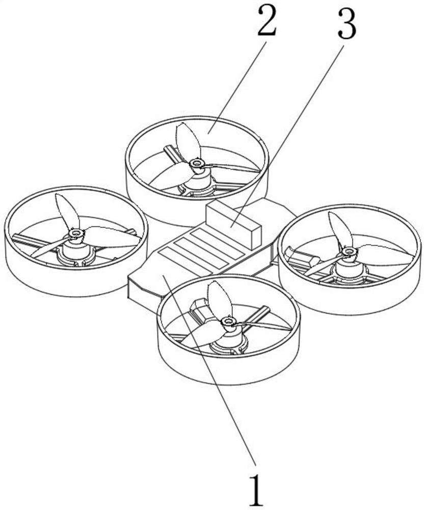
[0032] refer to figure 1 and figure 2 As shown, an unmanned aerial vehicle with a replaceable signal transmission mechanism includes a main body 1 and protective rings 2 symmetrically installed on both sides of the main body 1, and fan blades are installed inside the protective ring 2, and multiple groups of slot, and the inside of the slot is plugged with multiple sets of installation boxes 3, wherein,

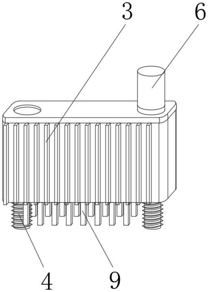
[0033] The copper post 9 installed on the bottom of the installation box 3 is plugged with the copper seat provided on the inner bottom surface of the slot.

[0034] refer to figure 2 A controller is installed inside the installation box 3, and the controller includes a bluetooth communicator, an infrared signal communicator, a wireless transceiver and a short-wave communicator.

[0035] refer to figure 2 , the outside of the installation box 3 is evenly bonded with cooling fins, and a ventilation slot is opened between two adjacent groups of installation boxes 3 .

...

Embodiment 2

[0044] refer to figure 1 and figure 2 As shown, an unmanned aerial vehicle with a replaceable signal transmission mechanism includes a main body 1 and protective rings 2 symmetrically installed on both sides of the main body 1, and fan blades are installed inside the protective ring 2, and multiple groups of slot, and the inside of the slot is plugged with multiple sets of installation boxes 3, wherein,

[0045] The copper post 9 installed on the bottom of the installation box 3 is plugged with the copper seat provided on the inner bottom surface of the slot.

[0046] refer to figure 2 A controller is installed inside the installation box 3, and the controller includes a bluetooth communicator, an infrared signal communicator, a wireless transceiver and a short-wave communicator.

[0047] refer to figure 2 , the outside of the installation box 3 is evenly bonded with cooling fins, and a ventilation slot is opened between two adjacent groups of installation boxes 3 .

...

Embodiment 3

[0056] refer to figure 1 and figure 2 As shown, an unmanned aerial vehicle with a replaceable signal transmission mechanism includes a main body 1 and protective rings 2 symmetrically installed on both sides of the main body 1, and fan blades are installed inside the protective ring 2, and multiple groups of slot, and the inside of the slot is plugged with multiple sets of installation boxes 3, wherein,

[0057] The copper post 9 installed on the bottom of the installation box 3 is plugged with the copper seat provided on the inner bottom surface of the slot.

[0058] refer to figure 2 A controller is installed inside the installation box 3, and the controller includes a bluetooth communicator, an infrared signal communicator, a wireless transceiver and a short-wave communicator.

[0059] refer to figure 2 , the outside of the installation box 3 is evenly bonded with cooling fins, and a ventilation slot is opened between two adjacent groups of installation boxes 3 .

...


PUM


Abstract

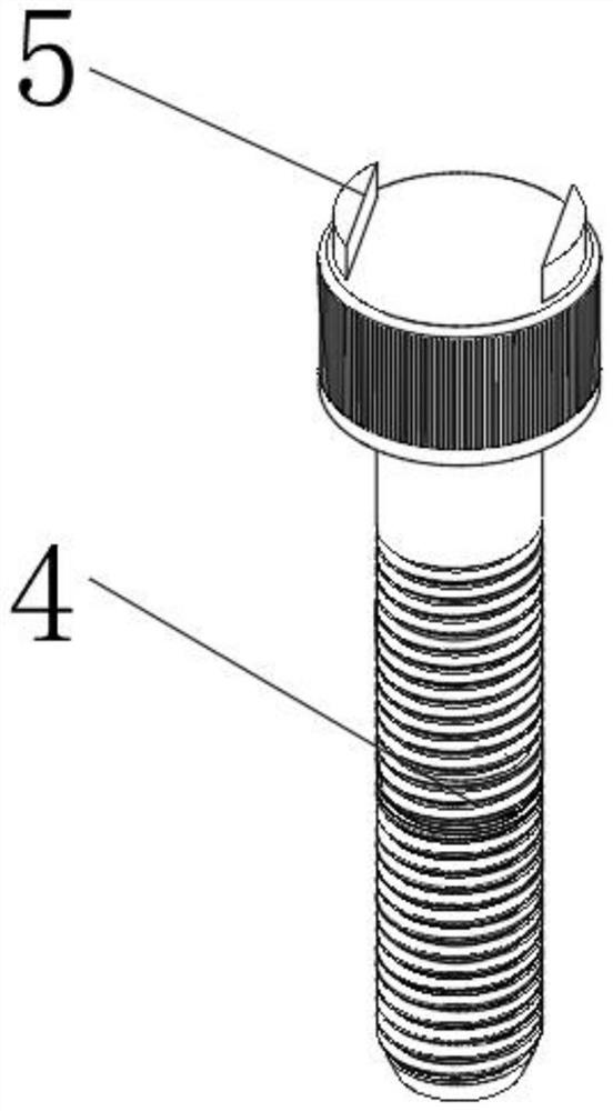
The invention discloses an unmanned aerial vehicle with a replaceable signal transmission mechanism. The unmanned aerial vehicle comprises a main body and protection rings symmetrically installed on the two sides of the main body, fan blades are installed in the protection rings, multiple sets of inserting grooves are formed in the top of the main body, multiple sets of installing boxes are inserted into the inserting grooves, and copper columns installed at the bottoms of the installing boxes are inserted into copper bases arranged on the inner bottom faces of the inserting grooves. Accordingto the unmanned aerial vehicle with a replaceable signal transmission mechanism, a controller is mounted in each installing box; different types of controllers can be replaced as required; radiatingfins are arranged outside the installing boxes; a ventilation groove is formed between every two adjacent installing boxes, so that the installing boxes are cooled and the moisture and dust in air are prevented from entering the vehicle; and positioning bolts are mounted at the bottoms of the installing boxes, and outer magnetic sheet is mounted at the top of each positioning bolt, so that the mounting stability of the installing boxes can be improved, and the installing boxes can be prevented from being randomly disassembled by non-staff.

Description

technical field [0001] The invention relates to the field of unmanned aerial vehicles, in particular to an unmanned aerial vehicle with a replaceable signal transmission mechanism. Background technique [0002] UAV is a kind of flying device controlled by wireless remote control. It does not need to be directly driven by humans. However, with the development of society and the continuous progress of industry, UAVs have gradually entered people's lives, ranging from small high-altitude shooting to large Cargo transportation, drones are constantly changing people's living standards; [0003] At present, when the existing drones are in use, if the internal components of the drone are damaged, the internal components can only be detected and repaired after the shell of the drone is disassembled. Complicated, making repairs requires professional staff to repair, and it is difficult for users to repair independently, resulting in difficult repairs. Secondly, non-staff can also di...

Claims


Application Information

Patent Timeline
Patent Type & Authority Applications(China)
IPC IPC(8): B64C27/08B64D27/20B64D47/02B64D47/08G03B11/00G03B15/02
CPCB64C27/08B64D27/20B64D47/02B64D47/08G03B11/00G03B15/02
Inventor 王大榕汪建军辛园庆王星王婷
Owner 马鞍山元辰网络科技有限公司
Learn More