
Double-electric-control flow control valve

A flow control valve and ESC technology, which is applied in safety valves, balance valves, valve devices, etc., can solve the problems of unsuitable control valves, low flow control accuracy, and inability to realize automatic control, etc., so as to achieve good automatic control effect and control The effect of high precision and convenient use

Active Publication Date: 2020-12-01
江苏慧呼吸医疗科技有限公司
View PDF10 Cites 0 Cited by
  • Summary
  • Abstract
  • Description
  • Claims
  • Application Information

AI Technical Summary

Problems solved by technology

[0002] The control valve consists of two main assemblies, the valve body assembly and the actuator assembly, which are divided into four series, single-seat series control valves, double-seat series control valves, sleeve series control valves and self-operated series control valves , the variants of the four types of valves can lead to many different applicable structures, each structure has its own special application, characteristics, advantages and disadvantages, although some control valves have wider application conditions than others, However, control valves are not suitable for all working conditions, and the best solution to enhance performance and reduce costs should be constructed together
[0003] At present, in daily life, oxygen is an important substance needed by our human body. Without oxygen, we cannot survive naturally. We cannot live without oxygen. I believe many people are familiar with the oxygen generator. Health preservation, disease treatment, etc., but the control valve on the existing oxygen generator is manually controlled, the flow control accuracy is low, and automatic control cannot be realized, and there are certain disadvantages in use.

Method used


Image

  • Double-electric-control flow control valve

Examples


Embodiment Construction

[0016] The present invention will be further described below in conjunction with the embodiments.

[0017] The following examples are used to illustrate the present invention, but cannot be used to limit the protection scope of the present invention. Conditions in the examples can be further adjusted according to specific conditions, and simple improvements to the method of the present invention under the premise of the concept of the present invention all belong to the scope of protection of the present invention.

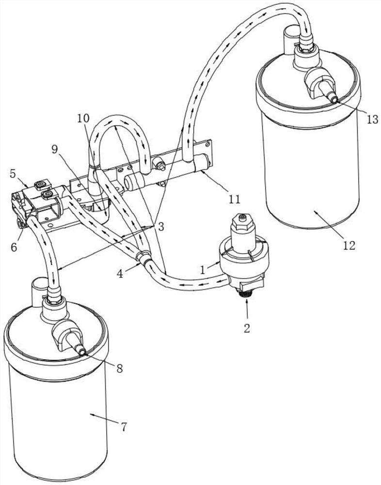
[0018] see figure 1 , the present invention provides a double-electric flow control valve, including a pressure regulating valve 1, the bottom of the pressure regulating valve 1 is provided with an air inlet 2, and the pressure regulating valve 1 regulates the gas pressure to be stable at 0.05Mpa (see figure 1 ); ensure that the gas enters at constant pressure.

[0019] The pressure regulating valve 1 is connected with one port of the three-way 4 through the sil...


PUM


Abstract

The invention discloses a double-electric-control flow control valve, and belongs to the technical field of miniature oxygen generators. The valve comprises a pressure regulating valve, and an air inlet is formed in the bottom of the pressure regulating valve; the pressure regulating valve is connected with one port of a tee joint through a silicone tube; one of the other two ports of the tee joint is jointly connected with a first electromagnetic valve and a second electromagnetic valve through silicone tubes; the other one of the other two ports of the tee joint is connected with a needle valve through a silicone tube, the first electromagnetic valve and the second electromagnetic valve are both connected with a humidifying bottle A through silicone tubes, and an air outlet A is formed in the top of the humidifying bottle A; and data feedback is performed through a flow and oxygen concentration sensor, under the action of the single-chip microcomputer, the single-chip microcomputer can control the flow of the air outlet A through the first electromagnetic valve and the second electromagnetic valve, meanwhile, the single-chip microcomputer can control the needle valve through a stepping motor, then the flow of an air outlet B can be controlled, double-flow output and control are achieved, the automatic control effect is good, the control precision is high, and use is more convenient and faster.

Description

technical field [0001] The invention belongs to the technical field of miniature oxygen generators, and in particular relates to a double-electricity regulating flow control valve. Background technique [0002] The control valve consists of two main assemblies, valve body assembly and actuator assembly, which are divided into four series, single-seat series control valve, double-seat series control valve, sleeve series control valve and self-operated series control valve , variations of the four types of valves can lead to many different applicable configurations, each with its own specific applications, features, advantages and disadvantages, although some control valves have wider application conditions than others, However, control valves are not suitable for all working conditions, and the best solution to enhance performance and reduce cost should be built together. [0003] At present, in daily life, oxygen is an important substance needed by our human body. Without o...

Claims


Application Information

Patent Timeline
Patent Type & Authority Applications(China)
IPC IPC(8): F17D3/01F17D1/02F16K17/20F16L41/02A61M16/16
CPCF17D3/01F17D1/02F16K17/205F16L41/023A61M16/16
Inventor 翁兆国罗语溪袁绍红
Owner 江苏慧呼吸医疗科技有限公司
Learn More