
Inflatable spliced antenna

An inflatable, antenna technology, applied in the direction of antenna, antenna support/installation device, electrical components, etc., can solve the problems of tracking blind area, large volume and complex structure, etc., and achieve the effect of solving the driving and tracking speed.

Pending Publication Date: 2020-12-01
NO 54 INST OF CHINA ELECTRONICS SCI & TECH GRP
View PDF0 Cites 0 Cited by
  • Summary
  • Abstract
  • Description
  • Claims
  • Application Information

AI Technical Summary

Problems solved by technology

Traditional azimuth and elevation antenna mounts and XY-type antenna mounts have disadvantages such as complex structure, large volume and mass, must have confluence rings and joints when the antenna rotates continuously, and have tracking blind spots, etc. The above problems will make its accuracy and speed more and more Become a restriction on the development of radio astronomy technology

Method used


Image

  • Inflatable spliced antenna
  • Inflatable spliced antenna
  • Inflatable spliced antenna

Examples


Embodiment Construction

[0025] The following Figure 1-8 The present invention is further described:

[0026] In a preferred embodiment of the present invention, a phased array antenna system of trusses, for example, such as figure 1 Indicated.

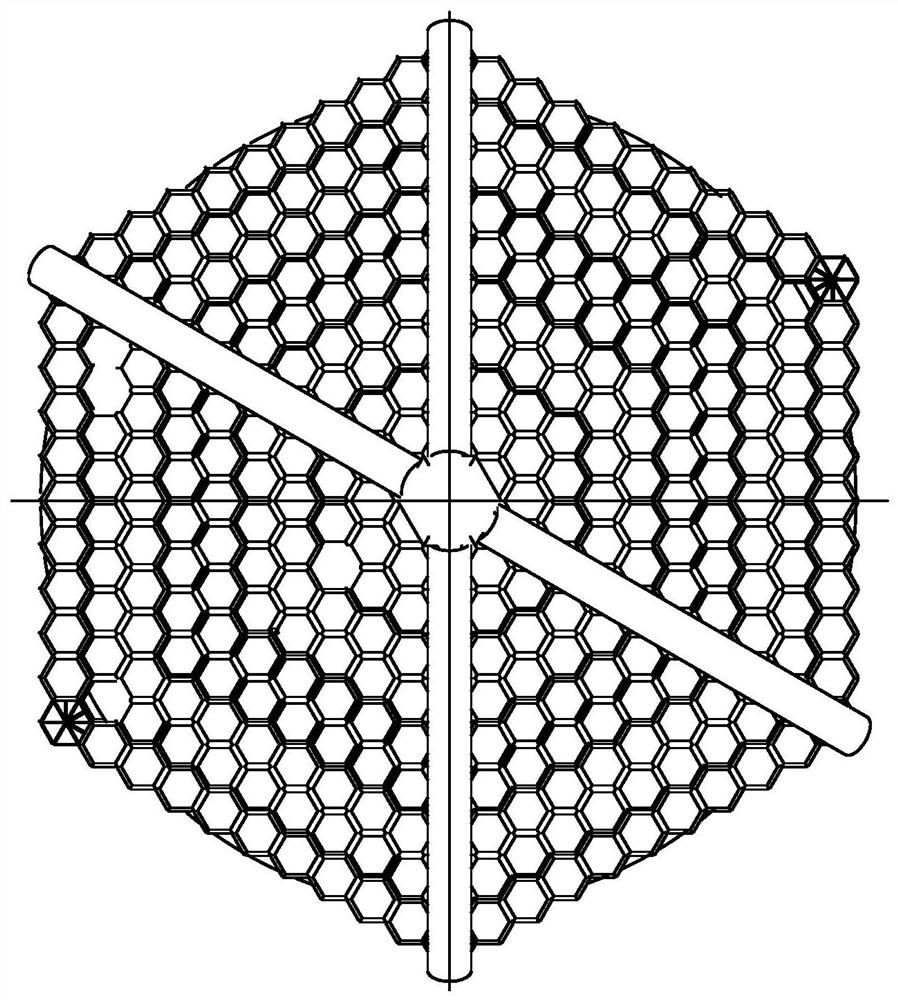
[0027] A pneumatic type splicing antenna comprising a main reflection surface and the secondary reflecting surface 12, the sub-reflecting surface erected on the main reflection surface.

[0028] Internal structure of the antenna unit of the invention is:

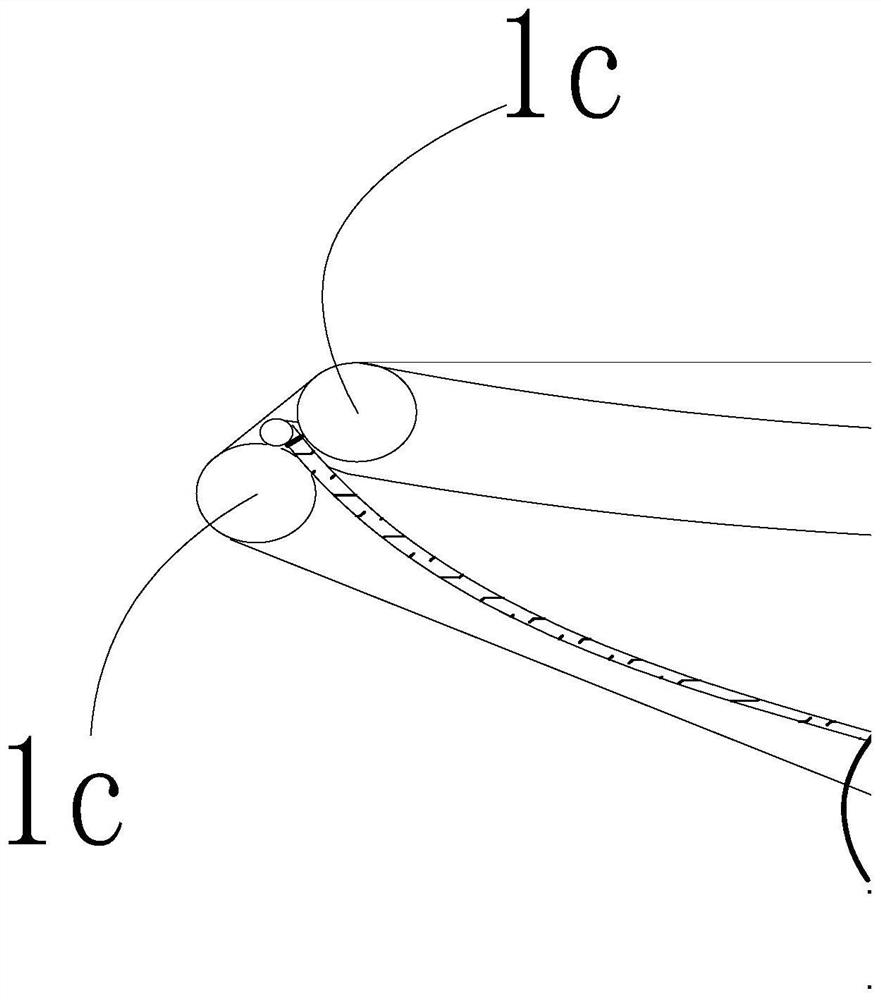
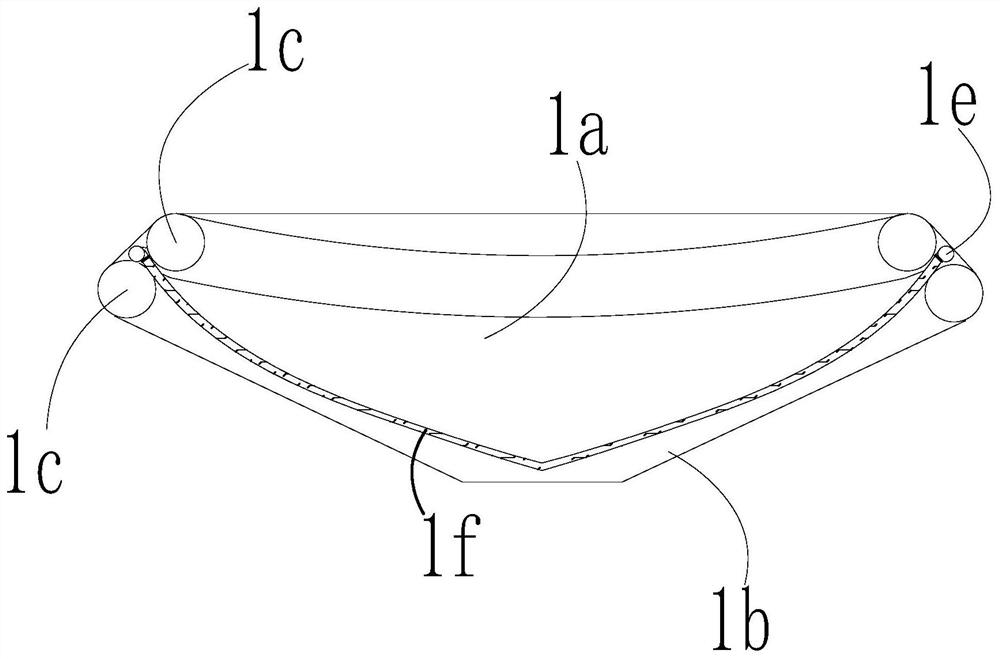
[0029] Main reflector antennas are spliced ​​together by a plurality of constituent units, each antenna element are composed of regular hexagon, each antenna element includes a lumen composition airbag, the airbag is provided with spacer 1f, the spacer hexagonal opening edge is concave, the balloon lumen compartment separated from each other on the isolated chamber and a lower chamber 1a. IB, an edge barrier on the inner wall is connected at the edge of the airbag,

[0030] Section of the column has a circular ...


PUM


Abstract

The invention discloses an inflatable antenna and a preparation process thereof. The inflatable antenna comprises antenna units, wherein the antenna unit is a closed air bag, a reflecting layer is arranged in each antenna unit and is a paraboloid, the plurality of antenna units are subjected to array splicing, and are spliced to form a paraboloid-shaped reflecting surface, an antenna bottom support is fixedly connected below the antenna units, and an antenna bottom frame is arranged below the antenna bottom support and is an azimuth-pitch antenna seat or a six-connecting-rod-pitch antenna seat. According to the invention, an inflation structure is introduced into the middle of a traditional antenna surface supporting structure, and the auxiliary surface, namely the supporting mechanism ofthe auxiliary surface, also adopts a brand-new inflation structure to solve the problems of reflection surface shielding and heavy burden of the antenna pedestal, so that the auxiliary surface shielding problem is solved, the wave transmission rate of the auxiliary surface arm is good, the shielding area of the auxiliary surface arm is reduced compared with the original rigid support, and the antenna reflectivity is improved.

Description

Technical field [0001] The present invention relates to a phased array antenna, and more particularly relates to an inflatable antenna splicing. Background technique [0002] To meet the demand for the development of radio astronomy, the antenna aperture made larger, increasing the operating frequency, the antenna structure is also more complex, so that the large antenna structure more complex, heavier weight, limiting its diameter increases, the structure of a large antenna design has become a large antenna design process vital link. Large antenna designs are usually optimized for antenna mounts structure, improve the structural rigidity of the seat back frame antenna to meet the overall stiffness and tracking speed of the antenna. The presence of complex structure, large volume mass, and joints must have slip rings when the antenna is rotated continuously, and there is a tracking blind disadvantages of the conventional azimuth and elevation antenna base XY type antenna pedestal...

Claims


Application Information

Patent Timeline
Patent Type & Authority Applications(China)
IPC IPC(8): H01Q19/19H01Q15/16H01Q1/12
CPCH01Q1/12H01Q15/16H01Q19/19
Inventor 李增科王大为董长胜肖松李沐曦胡熙悦
Owner NO 54 INST OF CHINA ELECTRONICS SCI & TECH GRP
Learn More