
Diamagnetic force structure

An anti-magnetic and permanent magnet technology, applied in the direction of magnetic circuit shape/style/structure, magnetic circuit, magnetic circuit rotating parts, etc., can solve problems such as irregular offset, increased installation difficulty, and component damage, etc., to achieve Effect of reducing interference, ensuring stability, ensuring stability and safety

Active Publication Date: 2020-12-01
CRRC XIAN YONGE JIELI WIND ENERGY CO LTD
View PDF6 Cites 3 Cited by
  • Summary
  • Abstract
  • Description
  • Claims
  • Application Information

AI Technical Summary

Problems solved by technology

After arriving at the project site, the two-lobed motors were assembled as a whole. Since the split-type direct-drive permanent magnet wind turbine contains permanent magnets, it has a strong magnetic field after assembly. During the separation and assembly of the product, it is affected by the magnetic pull. The pulling force is generally at least 10 tons, the movement of the workpiece cannot be controlled, and it is prone to irregular deviation, causing damage to parts and increasing the difficulty of installation

Method used


Image

  • Diamagnetic force structure
  • Diamagnetic force structure
  • Diamagnetic force structure

Examples


Embodiment Construction

[0027] In order to enable those skilled in the art to better understand the solution of the present invention, the present invention will be further described in detail below in conjunction with the accompanying drawings and specific embodiments. The terms "first" and "second" are used for descriptive purposes only, and cannot be understood as indicating or implying relative importance or implicitly specifying the quantity of indicated technical features. Thus, a feature defined as "first" and "second" may explicitly or implicitly include one or more of these features. In the description of the present invention, unless otherwise specified, "plurality" means two or more.

[0028] In order to make the object, technical solution and advantages of the present invention clearer, the technical solution of the present invention will be described in detail below. Apparently, the described embodiments are only some embodiments of the invention, not the complete embodiments. Based on...


PUM


Abstract

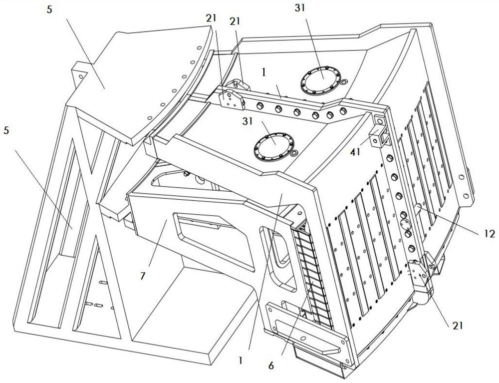
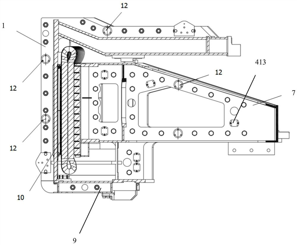
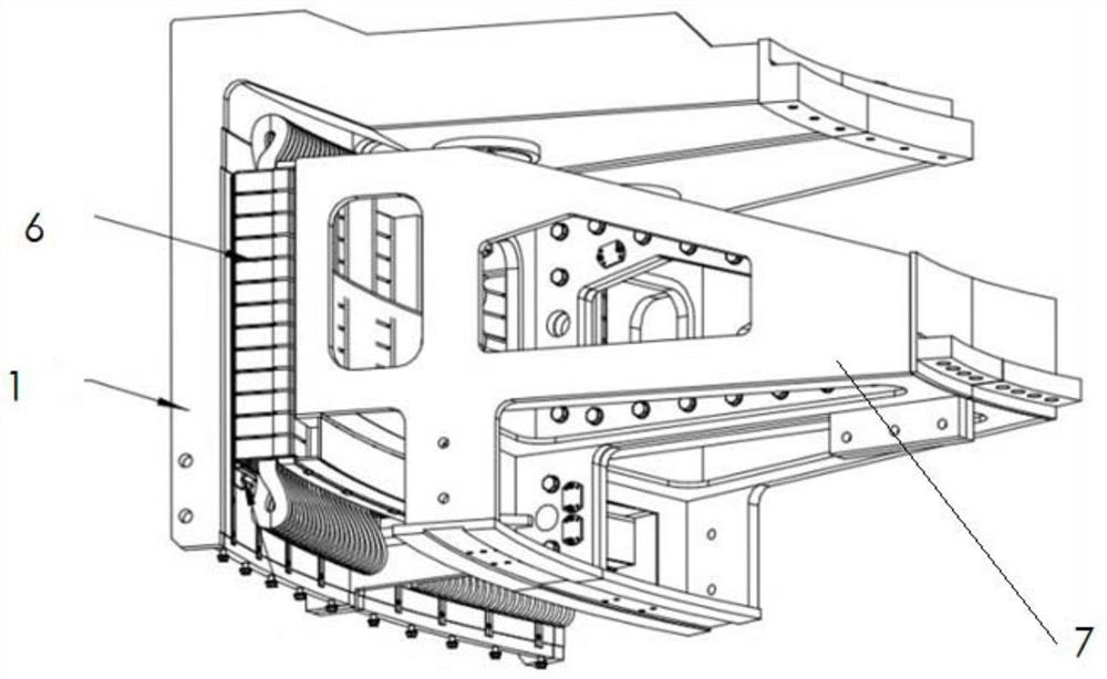
The invention discloses a diamagnetic force structure, which belongs to the technical field of wind driven generator mounting equipment, and solves the technical problem that a direct-drive wind driven generator in the prior art is inconvenient to mount on site due to the influence of magnetic force. The diamagnetic force structure comprises a rotor support matched with a split rotor and a statorsupport matched with a split stator, diamagnetic force assemblies are installed on the rotor support and the stator support, and the diamagnetic force assemblies can prevent the rotor assembly and / orthe rotor support from being influenced by a permanent magnet magnetic field when the generator is disassembled and assembled, and regular displacement is generated. Guiding installation and bufferingof the split type direct-drive permanent magnet wind driven generator in the assembling process can be achieved, and the stability in the assembling process is guaranteed.

Description

technical field [0001] The invention belongs to the technical field of installation equipment for wind power generators, and in particular relates to an anti-magnetic structure. Background technique [0002] The direct-drive wind turbine is an integral split structure, with an outer rotor, an inner stator, and a central shaft support. The rotor is a split semicircle structure, which is assembled by two semicircles and assembled on the rotor support. The rotor support mainly consists of a yoke, a rotor and a permanent magnet. The stator is a split structure, assembled by two semicircles, mainly composed of iron core, coil, conductive ring, phase lead-out wire and so on. The assembly process is that the stator is assembled into a full circle, the rotor is assembled into a full circle, the stator is fixed statically, and the rotor is lifted for assembly. The assembly method is a vertical assembly. After the assembly is completed, the two parts of the generator are separated as...

Claims


Application Information

Patent Timeline
IPC IPC(8): H02K15/00H02K15/03
CPCH02K15/00H02K15/03H02K15/0006H02K1/2788Y02E10/72H02K1/30H02K7/1838H02K2213/12
Inventor 李泽鹏宋晓骧左禾尚亚成熊恒张驰李晓菲武乐华
Owner CRRC XIAN YONGE JIELI WIND ENERGY CO LTD
Features
  • Generate Ideas
  • Intellectual Property
  • Life Sciences
  • Materials
  • Tech Scout
  • Unparalleled Data Quality
  • Higher Quality Content
  • 60% Fewer Hallucinations
Learn More