
Parallel diesel engine power generator system and control method therefor

An engine generator, diesel engine technology, applied in the direction of engine control, control generator, control system, etc., can solve the problems of different performance and life, diesel engine generator can not fully exert performance, etc., to improve efficiency, prolong The effect of fuel injection time and life extension

Inactive Publication Date: 2020-12-01
株式会社革我
View PDF9 Cites 0 Cited by
  • Summary
  • Abstract
  • Description
  • Claims
  • Application Information

AI Technical Summary

Problems solved by technology

However, since diesel engines are recovered from scrapped diesel vehicles to manufacture diesel generators, when multiple diesel generators are connected, the performance and life of each diesel engine of scrapped cars are different. When there is one The life of the diesel engine generator ends or the performance drops sharply, which leads to the problem that the entire diesel engine generator cannot fully perform

Method used


Image

  • Parallel diesel engine power generator system and control method therefor
  • Parallel diesel engine power generator system and control method therefor
  • Parallel diesel engine power generator system and control method therefor

Examples


Embodiment Construction

[0025] Hereinafter, embodiments of a parallel remanufactured diesel engine generator system and a control method thereof according to the present invention will be described with reference to the accompanying drawings.

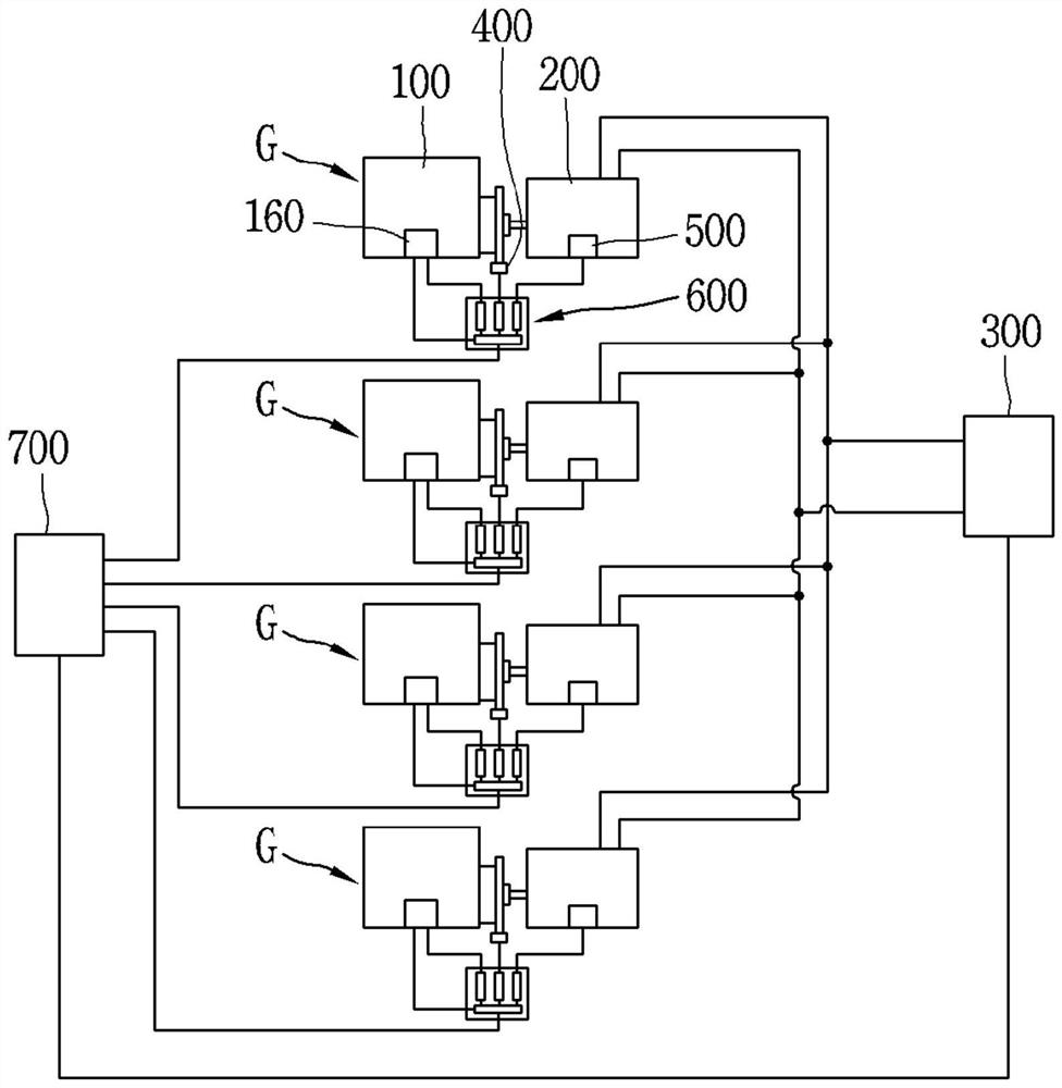
[0026] figure 1 is a block diagram showing a real-time example of a parallel remanufactured diesel engine generator system according to the present invention.

[0027] Such as figure 1 As shown, a real-time example of the parallel remanufactured diesel engine generator system according to the present invention includes: a plurality of diesel engine generators G connected in parallel; power distribution unit 300; engine output sensing unit 400; automatic voltage regulator 500 ; Engine generator control unit 600 ; System control unit 700 .

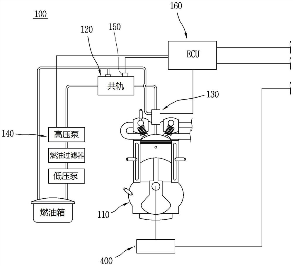
[0028] The diesel engine generator G includes: a scrap car diesel engine 100 recovered from a scrap diesel vehicle;

[0029] The end-of-life diesel engine 100 is recovered from end-of-life common rail diesel vehicles. En...


PUM


Abstract

The present invention relates to a parallel diesel engine power generator system and a control method therefor. The present invention comprises: a plurality of diesel engine power generators connectedin parallel to each other; a power distribution unit which collects power generated by each of the diesel engine power generators, and to which an external load is connected; engine output detectionunits which detect an output side RPM of a diesel engine and configure the diesel engine power generators, respectively; automatic voltage regulators provided in power generators configuring the diesel engine power generators, respectively; engine power generator control units for connecting electronic control units, which configure the diesel engine power generators, respectively, with the engineoutput detection units and the automatic voltage regulators, so as to control the diesel engine power generators; and a system control unit to which respective engine power generator control units ofthe diesel engine power generators are connected, wherein the power distribution unit is connected to the system control unit so that the system control unit distributes a load applied to the power distribution unit according to respective performance indices of the diesel engine power generators, so as to control the engine power generator control units. The present invention can increase the efficiency of power generation output from a plurality of diesel engine power generators connected in parallel and extend the lifetime of a diesel engine power generator.

Description

technical field [0001] The invention relates to a parallel diesel engine generator system and a control method. Background technique [0002] With the sharp increase in electricity consumption and difficulties in electricity production, the demand for self-generated electricity is increasing not only domestically but also around the world. [0003] Especially domestically, the need for self-generated electricity is increasing because of peak-value calculations and the application of weighted values ​​that increase with usage, resulting in electricity charges that can increase by up to five times the basic charge. In order to realize self-generation, generators using diesel engines are being used recently. [0004] Generators using diesel engines are divided into mechanical engine generators and electronic engine generators. [0005] Mechanical engine generators are less expensive than electronic engine generators, but have lower fuel efficiency and performance, and have di...

Claims


Application Information

Patent Timeline
Patent Type & Authority Applications(China)
IPC IPC(8): F02D29/06F02B63/04H02J3/38H02J3/46
CPCH02P9/48H02P9/04F02D29/06F02D25/00F02D2200/101F02B63/04H02J2300/10H02J3/381H02J3/46
Inventor 金承喆
Owner 株式会社革我
Learn More