Chemical paint stirring device with heating function

A technology of mixing device and chemical industry, which is applied to mixers with rotary mixing devices, accessories of mixers, transportation and packaging, etc., can solve the problems of inability to guarantee mixing of mixers, time-consuming and labor-consuming of mixers, splashing of paint, etc., and achieves a wide range of mixing. , Reasonable structure and strong practicability

Inactive Publication Date: 2020-12-04
张行江
View PDF0 Cites 4 Cited by
  • Summary
  • Abstract
  • Description
  • Claims
  • Application Information

AI Technical Summary

Problems solved by technology

[0005] Based on the fact that the existing mixer is time-consuming and labor-intensive, and holding the mixer all the time cannot ensure that the mixer can stir stably. If the mixer touches the inner wall of the paint, it will cause the paint to splash everywhere, and it may break the paint bucket in the worst case, causing human body damage. The technical problem of being hurt, the present invention proposes a chemical paint stirring device with heating function

Method used


Image

  • Chemical paint stirring device with heating function
  • Chemical paint stirring device with heating function
  • Chemical paint stirring device with heating function

Examples


Embodiment 1

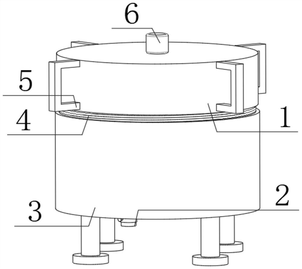
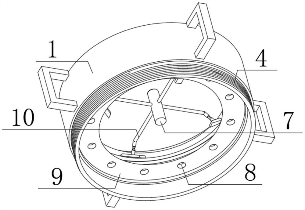
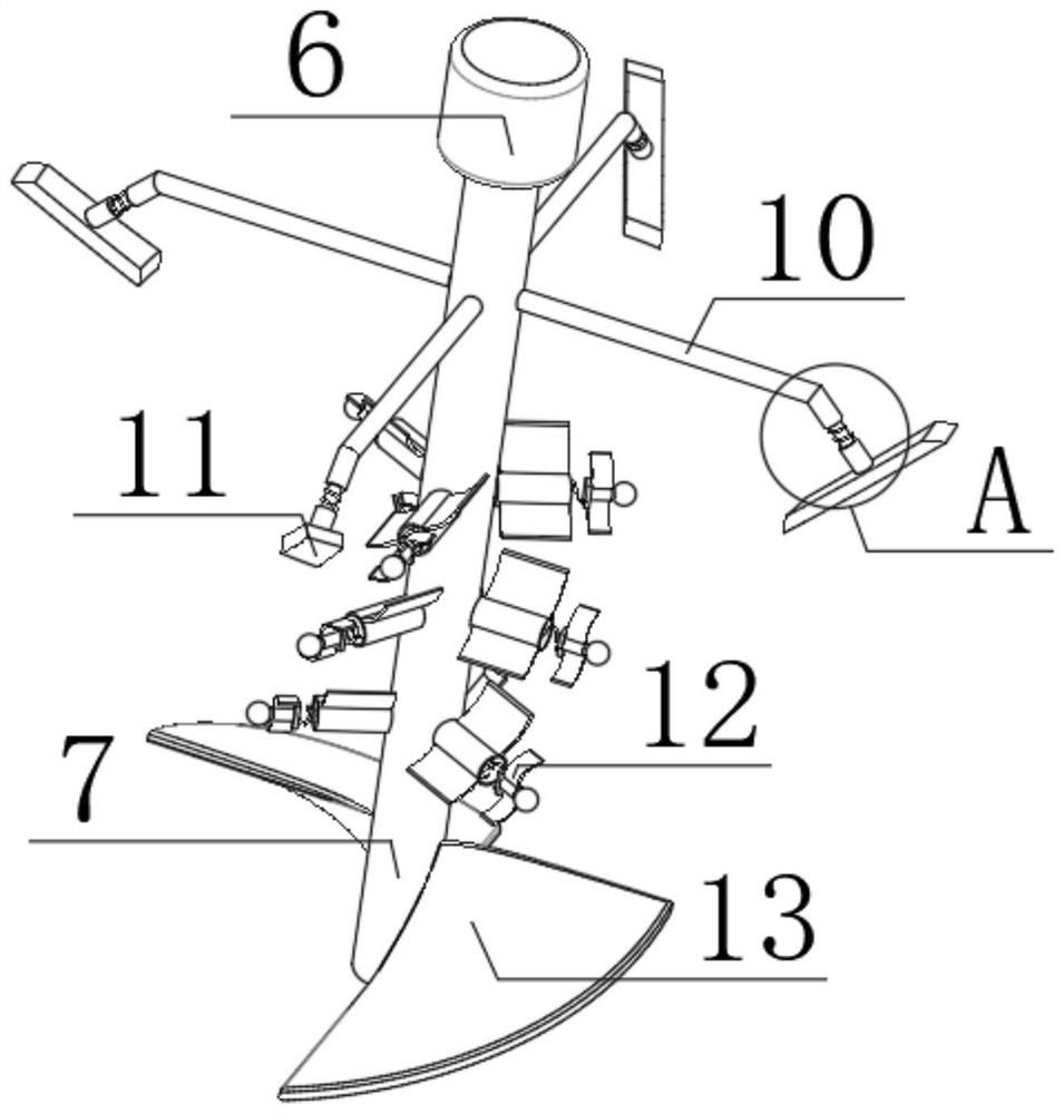
[0029] refer to Figure 1-5 , a chemical paint mixing device with a heating function, comprising a mixing tank 3, the top outer wall of the mixing tank 3 is provided with a first threaded groove 4, the inner wall of the first threaded groove 4 is threadedly connected with a box cover 1, and the box cover 1 The outer wall of the top is fixed with a motor 6 by bolts, and the output shaft of the motor 6 is connected with a rotating rod 7 through a coupling. The mounting plate is fixed by bolts, the outer wall of one side of the mounting plate is fixed with a sliding rod by bolts, one end of the sliding rod is fixed with a weight ball 15 by bolts, and the outer wall of the sliding rod is rotatably connected with a stirring plate 12, and the outer wall of the rotating rod 7 is fixed by bolts There are mixing plates 13 equidistantly distributed, the outer wall of the rotating rod 7 is provided with a liquid scraping mechanism, the inner wall of the box cover 1 is provided with a hea...

Embodiment 2

[0039] refer to Figure 6 , a chemical paint stirring device with a heating function. Compared with Embodiment 1, this embodiment also includes a thermal insulation foam 21 arranged on the inner wall of the heat storage tank.

[0040] When in use, the thermal insulation foam 21 can store the heat in the heat storage tank, thereby maintaining the heat in the heat storage tank for a long time, and then continuously heating the paint in the inner tube 19 .


PUM


Abstract

The invention belongs to the technical field of paint stirring, and particularly relates to a chemical paint stirring device with a heating function. The invention aims to solve the problems that an existing stirrer consumes considerable time and labor, the stirrer cannot be guaranteed to perform stable stirring when held by hand all the time, and if the stirrer touches the inner wall of a paint bucket, paint may splashes everywhere, or even the paint bucket is likely to be broken and harm is posed to human beings. According to a scheme provided by the invention, the chemical paint stirring device comprises a stirring bucket, wherein a first threaded groove is formed in the outer wall of the top of the stirring bucket, and a box cover is connected to the inner wall of the first threaded groove through threads; and a motor is fixed to the outer wall of the top of the box cover through bolts, and an output shaft of the motor is connected with a rotating rod through a coupling. Accordingto the chemical paint stirring device, a mixing plate is inclinedly arranged on the rotating rod to form an upward angle of 30 to 50 degrees; and by means of the arrangement, paint at the bottom of aninner bucket can be stirred upwards while the mixing plate rotates, and therefore, all the paint in the inner barrel can be fully stirred.

Description

technical field [0001] The invention relates to the technical field of paint stirring, in particular to a chemical paint stirring device with a heating function. Background technique [0002] The paint mixer is one of the components of the paint production equipment, that is, the mixing system. The paint mixer crushes, disperses, emulsifies, and mixes the paint. It is a new type of high-efficiency mixing equipment that operates at high speed through the upper and lower teeth of the dispersion plate. The cutting, impacting, pulverizing and dispersing can achieve the functions of rapid mixing, dissolving, dispersing and refining. It is an efficient equipment for stirring, dispersing and dissolving solids such as paint. In addition to the paint dispersing machine, the paint production equipment also includes a feeding system, a grinding system, a paint mixing system, a discharging and filtering system, a filling system, a control system, an operation platform, and a color past...

Claims


Application Information

Patent Timeline
Patent Type & Authority Applications(China)
IPC IPC(8): B01F7/16B01F7/18B01F11/00B01F15/00B01F15/06
CPCB01F27/051B01F27/0542B01F27/80B01F27/90B01F31/443B01F35/123B01F2035/99B01F35/92B01F2101/30
Inventor 张行江
Owner 张行江
Why Eureka
Try Eureka