
Metal can body forming processing method

A technology of forming processing and metal cans, which is applied in metal processing equipment, forming tools, manufacturing tools, etc., can solve the problems of falling molds and hurting people, safety hazards of personnel who replace molds, and long time consumption of molds, etc., to save money Time, efficiency improvement effect

Inactive Publication Date: 2020-12-04
尚玉磊
View PDF7 Cites 3 Cited by
  • Summary
  • Abstract
  • Description
  • Claims
  • Application Information

AI Technical Summary

Problems solved by technology

[0003] The can body of the two-piece can is a thin metal plate, which is stretched and deformed by a punch through a stretching mold, so that the bottom and body of the tank are connected into one. The following problems usually exist when processing two-piece cans in the prior art: Due to the variety of shapes of metal cans, when manufacturing cans of different shapes, it is necessary to frequently disassemble the upper and lower molds on the punching machine, and it takes a long time to disassemble and replace the molds, thereby reducing the production efficiency of two-piece cans; And the stamping die is heavy because of its heavy weight, so when disassembling and replacing it, it is easy to cause the die to fall and hurt people because the person who replaces the die cannot hold the stamping die firmly. There are safety hazards for personnel who change molds
[0004] Regarding the technical problems existing in the current process of manufacturing two-piece cans with a punching machine through a stretch forming mold, personnel in the related technical field have made research and made adaptation improvements, such as the Chinese invention patent No. 2019103703088 A metal The can manufacturing process can produce metal cans with novel shapes, but the above-mentioned problems are not mentioned

Method used


Image

  • Metal can body forming processing method
  • Metal can body forming processing method
  • Metal can body forming processing method

Examples


Embodiment Construction

[0045] The embodiments of the present invention will be described in detail below with reference to the accompanying drawings, but the present invention can be implemented in many different ways defined and covered by the claims.

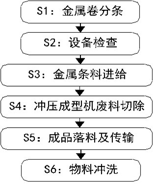
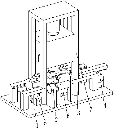
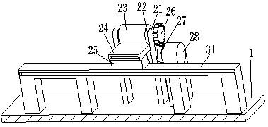
[0046] Such as Figure 1 to Figure 10 As shown, a method for forming and processing a metal tank body. The method for forming and processing a metal tank body adopts the following metal tank body forming and processing device. The metal tank body forming and processing device includes a base 1, a feeding mechanism 2, a supporting mechanism 3, a stamping Die mechanism 4, drive mechanism 5, transmission mechanism 6, stamping upper mold mechanism 7 and waste box 8, feeding mechanism 2 is installed on the front side of the upper end of the base 1, and a support mechanism is installed on the rear side of the feeding mechanism 2 on the upper end surface of the base 1 3. The middle part of the support mechanism 3 is installed with a stamping lower die mech...


PUM


Abstract

The invention relates to a metal can body forming processing method which adopts a following metal can body forming processing device. The metal can body forming processing device comprises a base, afeeding mechanism, a supporting mechanism, a stamping lower die mechanism, a driving mechanism, a conveying mechanism, a stamping upper die mechanism and a waste box, wherein the feeding mechanism isarranged at the front side of the upper end face of the base; the supporting mechanism is arranged on the upper end face of the base and located at the rear side of the feeding mechanism; the stampinglower die mechanism is arranged in the middle of the supporting mechanism in a sliding fit mode; the driving mechanism is arranged at the lower end of the stamping lower die mechanism; the conveyingmechanism is arranged on the upper end face of the base and located at the right side of the driving mechanism; the stamping upper die mechanism is arranged at the upper end of the supporting mechanism; and the waste box is arranged on the upper end face of the base and located at the rear side of the supporting mechanism. According to the metal can body forming processing method, the problems oflow efficiency and the like when a stamping die is disassembled and replaced in the process of manufacturing a two-piece can by using a punch press through stretching a forming die can be solved.

Description

technical field [0001] The invention relates to the field of metal manufacturing, in particular to a method for forming and processing a metal tank body. Background technique [0002] In daily life, you can often see a can-shaped packaging box made of some metal. The metal cans are mainly classified into three-piece cans and two-piece cans according to the manufacturing method, and the two-piece cans came out in the middle of the 20th century. The entire packaging can is composed of two pieces, namely the can body and the can lid, so it is called a two-piece can. [0003] The can body of the two-piece can is a thin metal plate, which is stretched and deformed by a punch through a stretching mold, so that the bottom and body of the tank are connected into one. The following problems usually exist when processing two-piece cans in the prior art: Due to the variety of shapes of metal cans, when manufacturing cans of different shapes, it is necessary to frequently disassemble t...

Claims


Application Information

Patent Timeline
IPC IPC(8): B21D37/04B21D22/02B21D43/09B21D43/20B21D43/28B21D45/02
CPCB21D37/04B21D22/02B21D43/28B21D43/20B21D43/09B21D45/02
Inventor 尚玉磊
Owner 尚玉磊
Learn More