Cambered surface burnishing device for machining inner wall of crane hydraulic oil cylinder body

A technology of hydraulic oil cylinder and polishing device, which is applied to grinding/polishing safety device, surface polishing machine tool, grinding drive device, etc., can solve the problems of hydraulic oil cylinder block being unavailable, staff resting, and dust collection being impossible, etc. To achieve the effect of easy polishing operation, reduced labor intensity and strong practicability

Inactive Publication Date: 2020-12-04
铁美珍
View PDF11 Cites 4 Cited by
  • Summary
  • Abstract
  • Description
  • Claims
  • Application Information

AI Technical Summary

Problems solved by technology

[0004] The object of the present invention is to provide an arc surface polishing device for processing the inner wall of the hydraulic cylinder of a crane, so as to solve the problem that the existing polishing device proposed in the above background technology cannot collect dust, cannot fix hydraulic cylinders of different sizes and cannot supply Problem with staff rest

Method used


Image

  • Cambered surface burnishing device for machining inner wall of crane hydraulic oil cylinder body
  • Cambered surface burnishing device for machining inner wall of crane hydraulic oil cylinder body
  • Cambered surface burnishing device for machining inner wall of crane hydraulic oil cylinder body

Examples


Embodiment 1

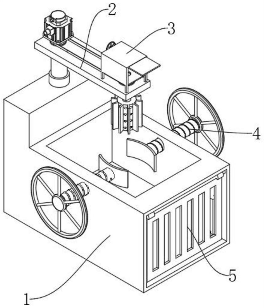
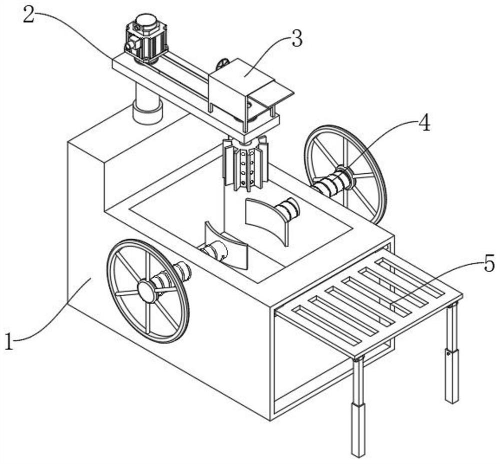
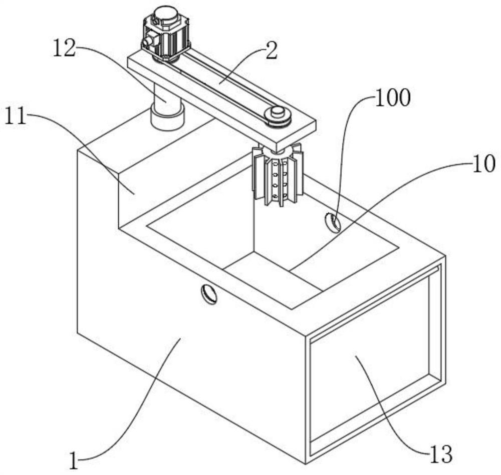
[0035] see Figure 1-Figure 11 As shown, this embodiment provides an arc surface polishing device for processing the inner wall of the hydraulic cylinder of a crane, including a polishing frame 1, a side plate 11 is arranged on the top of the polishing frame 1 near the edge, and an electric push rod 12 is arranged on the top of the side plate 11 , the electric push rod 12 piston rods are provided with a moving plate 2, and the electric push rod 12 piston rods drive the moving plate 2 to move up and down above the polishing frame 1, so as to facilitate adjustment of the distance from the moving plate 2 to the polishing frame 1 and ensure the integrity of the structure.

[0036] Specifically, the working principle of the electric push rod 12 is as well known to those skilled in the art. The rotary motion of the motor drives the worm gear transmission, which is transmitted to the screw rod for rotary motion, and the rotary motion of the screw rod drives the nut to perform linear m...


PUM


Abstract

The invention relates to the technical field of burnishing devices, in particular to a cambered surface burnishing device for machining the inner wall of a crane hydraulic oil cylinder body. The burnishing device comprises a burnishing frame. A side plate is arranged at the top of the burnishing frame, an electric push rod is arranged at the top of the side plate, a movable plate is arranged on apiston rod of the electric push rod, a rotating rod is rotationally arranged on the surface of the movable plate, a dust collecting box is rotationally arranged at the top of the rotating rod, the bottom of the rotating rod communicates with a burnishing roll, a plurality of burnishing plates are arranged on the outer wall of the burnishing roll, a plurality of through holes are formed in the outer wall of the burnishing roll and communicate with the interior of the dust collecting box, a fixed slot is formed in the top of the burnishing frame, both sides of the fixed slot are in threaded connection with fixing devices, the fixing devices are located right under the burnishing roll, a cambered plate is rotationally arranged at the end part of a corresponding screw, and a folding stool is rotationally arranged in a folding groove in the outer wall of the burnishing frame. According to the burnishing device, dust can be conveniently collected, hydraulic oil cylinder bodies of different sizes can be fixed, and workers can have a rest on the burnishing device.

Description

technical field [0001] The invention relates to the technical field of polishing devices, in particular to an arc surface polishing device for processing the inner wall of a hydraulic oil cylinder of a crane. Background technique [0002] The hydraulic cylinder is a hydraulic actuator that converts hydraulic energy into mechanical energy and performs linear reciprocating motion (or swinging motion); it has a simple structure and reliable operation; when it is used to realize reciprocating motion, the deceleration device can be eliminated, and there is no transmission gap , the movement is stable, so it is widely used in cranes. In the production of hydraulic cylinders, the inner wall of the cylinder needs to be processed and polished. Polishing refers to the use of mechanical, chemical or electrochemical effects to reduce the surface roughness of the workpiece to obtain a bright finish. , The processing method of flat surface; [0003] However, the current polishing device ...

Claims


Application Information

Patent Timeline
Patent Type & Authority Applications(China)
IPC IPC(8): B24B29/02B24B55/06B24B55/12B24B41/06B24B47/12B24B41/00A47C9/02A47C4/04A47C7/00
CPCA47C4/04A47C7/002A47C9/02B24B29/02B24B41/00B24B41/06B24B47/12B24B55/06B24B55/12
Inventor 谭宇岐铁钟铁美珍
Owner 铁美珍
Why Eureka
Try Eureka