
Circuit board processing device for electrical components

A technology for processing devices and electrical components, applied in metal processing, metal processing equipment, manufacturing tools, etc., to achieve the effect of convenient and fast operation and improved efficiency

Inactive Publication Date: 2020-12-04
SUZHOU GUIGUO ELECTRONICS
View PDF0 Cites 1 Cited by
  • Summary
  • Abstract
  • Description
  • Claims
  • Application Information

AI Technical Summary

Problems solved by technology

[0002] Multiple electronic components, such as capacitors, are often inserted into the circuit board, so it is necessary to drill the circuit board; Manually match the specifications, that is, you need to first check the size of the capacitor pins, and then select a drill with a suitable size from a pile of drills; but this selection process requires manual checks one by one. When there are many capacitor specifications, this method is obviously no longer applicable

Method used


Image

  • Circuit board processing device for electrical components
  • Circuit board processing device for electrical components
  • Circuit board processing device for electrical components

Examples


Embodiment 1

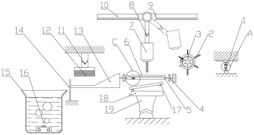
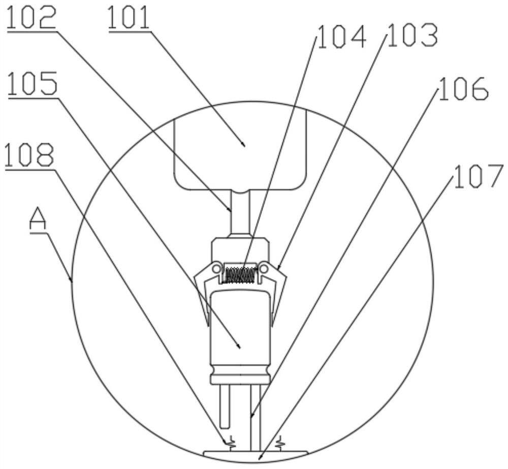
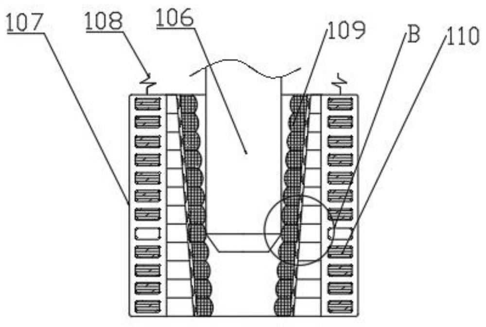
[0026] see also Figure 1-7 A circuit board processing device for electrical components comprises a drill 2 and a drill drive module 7, wherein the drill 2 is connected to the drill drive module 7, and the drill drive module 7 drives it to drill holes on the surface of the circuit board 6; the side of the drill drive module 7 is provided with a pre-judgment mechanism 1 for selecting the specifications of the drill 2; the pre-judgment mechanism 1 comprises a clamping module and a pre-judgment module; the clamping module comprises a telescopic rod 101 and a claw seat 102, One end of the telescopic rod 101 is slidably arranged on the wall, and the other end is fixedly connected with one end of the claw base 102, and the other end of the claw base 102 is rotatably connected with two claws 103, which are elastically connected by a first spring 104. The pre-judgment module includes a pre-judgment housing 107 and a movable block 109, and the pre-judgment housing 107 is arranged below the ...

Embodiment 2

[0032] In order to further improve the processing efficiency of the circuit board 6, an improvement is added on the basis of Embodiment 1. The improvement is as follows: Please refer to Figure 1-7 A drill driving module 7 is arranged at the side of the cutter head 3, a connecting hole matched with the drill 2 is arranged below the drill driving module 7, a driving block 20 is slidably arranged at the side, and a rocker arm 8 is rotatably connected to the driving block 20, and the rocker arm 8 is a telescopic arm with telescopic function; The rocker arm 8 is rotatably connected to the slide block 9, and the slide block 9 is slidably connected to the slide bar 10, which is fixedly connected to the wall.

[0033] The drill pin driving module 7 can be divided into three states in the whole process. The first state is the working state, that is, driving the drill pin 2 for drilling; Secondly, the tool changing state, that is, with the cooperation of the driving block 20, the rocker arm...


PUM


Abstract

The invention discloses a circuit board processing device for electrical components. The device comprises a drill point and a drill point driving module; a pre-judging mechanism for selecting the specification of the drill point is arranged on the side surface of the drill point driving module; and the pre-judging mechanism comprises a clamping module and a pre-judging module. During use, a capacitor is clamped by the clamping module, pins installed on the capacitor are driven by a telescopic rod to be inserted into a pre-judging shell, when the pins touch a certain pair of movable blocks, themovable blocks can slide in movable blocks on the two adjacent sides, a loop is connected through connection of an electric piece set, then an electric signal can be transmitted into an indicator lamp through a second wire to turn on the indicator lamp, therefore, a user can directly determine the diameter of the pins by observing whether the indicator lamp is turned on or not; add the electric signal can also be transmitted to a cutter head through a first wire and drives the cutter head to rotate to a proper tool changing position, so that the drill point driving module is able to change atool quickly.

Description

Technical field [0001] The invention relates to the field of electronic component processing, in particular to a circuit board processing device for electrical components. technical background [0002] Many electronic components, such as capacitors, are often inserted into the circuit board, so it is necessary to drill the circuit board. Firstly, different drill pins are selected according to the thickness of the pins of electronic components. In the process of selecting drill pins, it is necessary to manually match the specifications, that is, it is necessary to check the size of the capacitor pins first, and then select the drill pins with appropriate size from a pile of drill pins. However, this selection process needs to be checked manually. When there are many specifications of capacitors on a circuit board, this method is obviously no longer applicable. Inventive content [0003] The purpose of the present invention is to provide a circuit board processing device for elect...

Claims


Application Information

Patent Timeline
IPC IPC(8): B26F1/16B26D7/26B26D7/27B26D7/06B26D7/32B24B27/033B08B3/10
CPCB08B3/106B24B27/033B26D7/0616B26D7/2614B26D7/27B26D7/32B26D2007/322B26F1/16B26F2210/08
Inventor 谈星
Owner SUZHOU GUIGUO ELECTRONICS
Learn More