Device and method for improving 3D printing precision through DMD dynamic exposure

A 3D printing and precision technology, applied in the field of 3D printing, can solve the problems of smaller printing area, reduced lens optical magnification, 3D printing accuracy can not meet the requirements, etc., to achieve high-precision printing effect and save the number of drivers.

Active Publication Date: 2020-12-04
合肥众群光电科技有限公司
View PDF16 Cites 0 Cited by
  • Summary
  • Abstract
  • Description
  • Claims
  • Application Information

AI Technical Summary

Problems solved by technology

[0002] With the development of intelligent manufacturing technology, the rapid prototyping of molds, or the direct printing of parts is now a hot spot in intelligent manufacturing research. DMD-based 3D printing technology is an important technical solution in 3D printing. It has fast printing speed, The advantage of high precision, but now the accuracy requirements for 3D printing are constantly increasing, and the ordinary 3D printing accuracy cannot meet the requirements. The method of the present invention is a method to improve the 3D printing accuracy of DMD
[0003] In the 3D printing of small-sized parts, in the currently used DMD printing, the worktable only moves up and down with the Z axis to change the height of the printed object, so that the position of each lens on the DMD and the imaging surface is relatively static , the printing accuracy depends on the size of the light spot on the imaging rubber surface of the lens on each DMD. In this way, if the printing accuracy is to be improved, the optical magnification of the lens must be reduced, and the problem caused by reducing the optical magnification is that the printing area becomes smaller. Small

Method used


Image

  • Device and method for improving 3D printing precision through DMD dynamic exposure
  • Device and method for improving 3D printing precision through DMD dynamic exposure
  • Device and method for improving 3D printing precision through DMD dynamic exposure

Examples


Embodiment Construction

[0021] A method of using DMD dynamic exposure to improve the device of 3D printing accuracy, comprising the following steps:

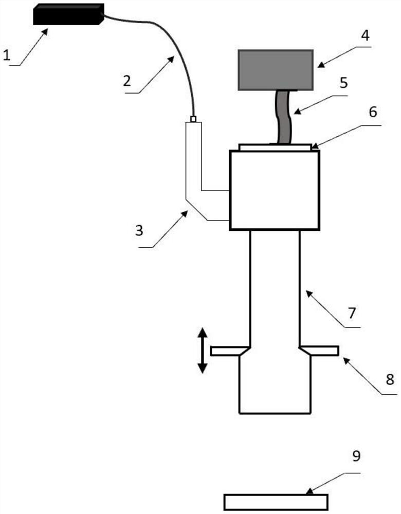
[0022] S1. Assembly system; such as figure 1 As shown, the laser 1 in the system enters the illumination lens 3 through the optical fiber 2, and the illumination lens 3 turns the point light source into a uniform surface light source and irradiates it on the DMD6 on the gantry 8, and the light emitted by the DMD6 passes through the imaging lens 7 is irradiated on the workbench 9, and the DMD control and data processing system 4 is connected to the DMD6 signal through the flexible cable 5;

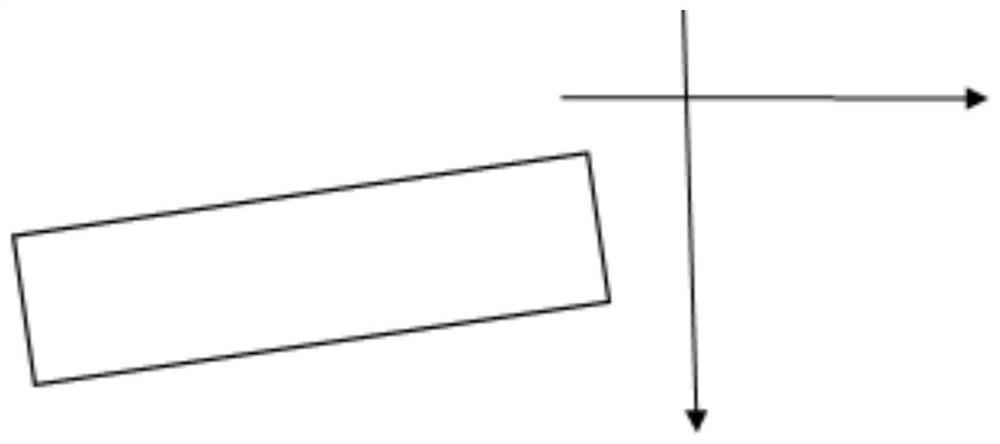
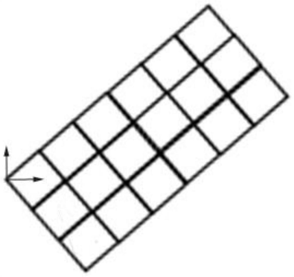
[0023] S2. Adjust the DMD6 on the gantry 8 so that the image formed by the DMD6 forms a set angle with the horizontal movement direction of the workbench 9 . The image formed by DMD6 and the horizontal movement direction of workbench 9 are as follows: figure 2 As shown, the present invention takes the set angle as 45° as an example, the optical magnification of t...


PUM


Abstract

The invention discloses a method for improving 3D printing precision through DMD dynamic exposure. The method comprises the following steps that S1, a system is assembled; S2, the angle of a DMD on aportal frame is adjusted; S3, a DMD control and data processing system cuts and fills bottommost data of a to-be-printed 3D model stored in the system and then sends the bottommost data to the DMD, and the DMD transfers the obtained data corresponding to the bottommost layer to a photosensitive material of a workbench and solidifies the data; S4, the distance between the workbench and the DMD is increased to be a first unit distance D1, and the workbench and / or the DMD are / is horizontally moved to deviate by a second unit distance D2; the DMD control and data processing system controls the to-be-printed data model stored in the system to move upwards by the first unit distance D1 in the height direction, the data at the height is cut, filled and sent to the DMD, and the DMD transfers the obtained data to the photosensitive material of the workbench and solidifies the data; and S5, the step S4 is circulated until the exposure of a whole 3D printed piece is completed. According to the method, the printed piece is moved to DMD lenses in different rows, and therefore a printing effect with higher precision can be achieved.

Description

technical field [0001] The invention relates to the technical field of 3D printing, in particular to a device and method for improving the precision of 3D printing by using DMD dynamic exposure. Background technique [0002] With the development of intelligent manufacturing technology, the rapid prototyping of molds, or the direct printing of parts is now a hot spot in intelligent manufacturing research. DMD-based 3D printing technology is an important technical solution in 3D printing. It has fast printing speed, The advantage of high precision, but now the precision requirements for 3D printing are constantly increasing, and the ordinary 3D printing precision cannot meet the requirements. The method of the present invention is a method for improving the 3D printing precision of DMD. [0003] In the 3D printing of small-sized parts, in the currently used DMD printing, the worktable only moves up and down with the Z axis to change the height of the printed object, so that th...

Claims


Application Information

Patent Timeline
Patent Type & Authority Applications(China)
IPC IPC(8): B29C64/268B29C64/20B29C64/393B33Y30/00B33Y50/02
CPCB29C64/268B29C64/20B29C64/393B33Y30/00B33Y50/02Y02P10/25
Inventor 陈修涛
Owner 合肥众群光电科技有限公司
Why Eureka
Try Eureka