Control method, device and equipment for recycling torque and vehicle
A control method and technology of a control device, which are applied in vehicle components, electric vehicles, transportation and packaging, etc., can solve problems such as poor drivability, ABS intervention, and vehicle clutter.
- Summary
- Abstract
- Description
- Claims
- Application Information
AI Technical Summary
Problems solved by technology
Method used
Image
Examples
Embodiment 1
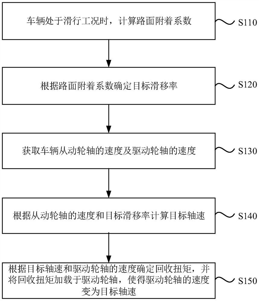
[0055] figure 2 It is a flow chart of a recovery torque control method provided by Embodiment 1 of the present invention. This embodiment is applicable to the situation where an electric vehicle controls recovery torque under coasting conditions. The method can be implemented by a control device for recovery torque Execution, such as figure 1 As shown, the method specifically includes the following steps:
[0056] Step 110, when the vehicle is in a sliding condition, calculate the road surface adhesion coefficient.
[0057] Among them, the vehicle is An electric vehicle does not involve an engine vehicle. Among them, the coasting condition can be understood as the vehicle coasting with gears, that is, the foot leaves the accelerator pedal, and the driving motor outputs negative torque to recover a part of the kinetic energy while the vehicle decelerates, and converts it into electric energy of the battery.
[0058] Specifically, the process of calculating the road surfac...
Embodiment 2
[0089] Figure 8 It is a structural schematic diagram of a recovery torque control device provided by an embodiment of the present invention. Such as Figure 8 As shown, the device includes: a road surface adhesion coefficient calculation module 210 , a target slip rate determination module 220 , an axle speed acquisition module 230 , a target axle speed calculation module 240 and a regenerative torque determination module 250 .
[0090] The road surface adhesion coefficient calculation module 210 is used to calculate the road surface adhesion coefficient when the vehicle is in a sliding condition;
[0091] A target slip rate determination module 220, configured to determine the target slip rate according to the road surface adhesion coefficient;
[0092] The wheel shaft speed acquisition module 230 is used to obtain the speed of the vehicle driven wheel shaft and the speed of the driving wheel shaft;
[0093] A target shaft speed calculation module 240, configured to calcu...
Embodiment 3
[0107] Figure 9 It is a schematic structural diagram of a computer device provided by Embodiment 3 of the present invention. Figure 9 A block diagram of a computer device 312 suitable for implementing embodiments of the invention is shown. Figure 9 The computer device 312 shown is only an example, and should not impose any limitation on the functions and scope of use of the embodiments of the present invention. Device 312 is a computing device typical of regenerative torque control functions.
[0108] Such as Figure 9 As shown, computer device 312 takes the form of a general-purpose computing device. Components of computer device 312 may include, but are not limited to: one or more processors 316, storage 328, bus 318 connecting various system components including storage 328 and processor 316.
[0109] Bus 318 represents one or more of several types of bus structures, including a memory bus or memory controller, a peripheral bus, an accelerated graphics port, a proces...
PUM
 Abstract
Description
Claims
Application Information
 - R&D
- Intellectual Property
- Life Sciences
- Materials
- Tech Scout
- Unparalleled Data Quality
- Higher Quality Content
- 60% Fewer Hallucinations
Browse by: Latest US Patents, China's latest patents, Technical Efficacy Thesaurus, Application Domain, Technology Topic, Popular Technical Reports.
© 2025 PatSnap. All rights reserved.Legal|Privacy policy|Modern Slavery Act Transparency Statement|Sitemap|About US| Contact US: help@patsnap.com


