High-altitude hoisting and quick release device for generator

A technology for generators and conveyor belts, applied to conveyors, conveyor objects, transportation and packaging, etc., can solve the problems of increasing labor intensity, reducing work efficiency, and inconvenient operation

Active Publication Date: 2020-12-04
SHANXI INSTALLATION GRP CO LTD
View PDF5 Cites 1 Cited by
  • Summary
  • Abstract
  • Description
  • Claims
  • Application Information

AI Technical Summary

Problems solved by technology

[0003] In the prior art, the lifting of the generator requires manual loading and unloading, which...

Method used


Image

  • High-altitude hoisting and quick release device for generator
  • High-altitude hoisting and quick release device for generator
  • High-altitude hoisting and quick release device for generator

Examples


Embodiment 1

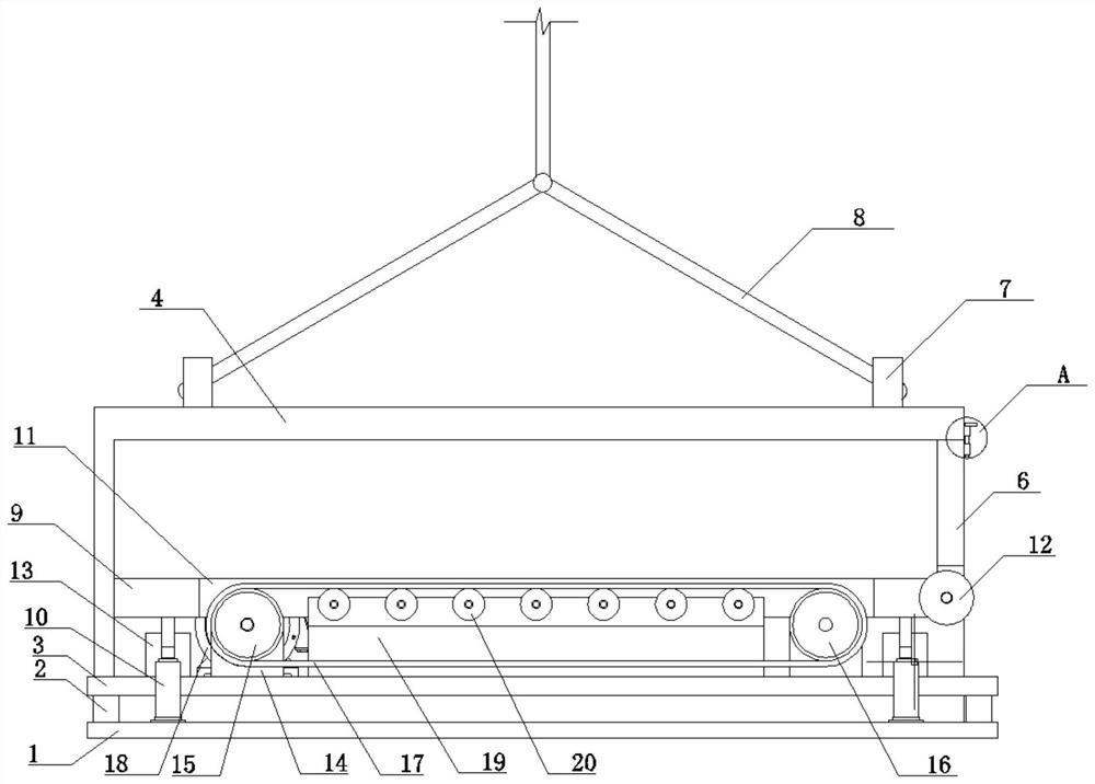
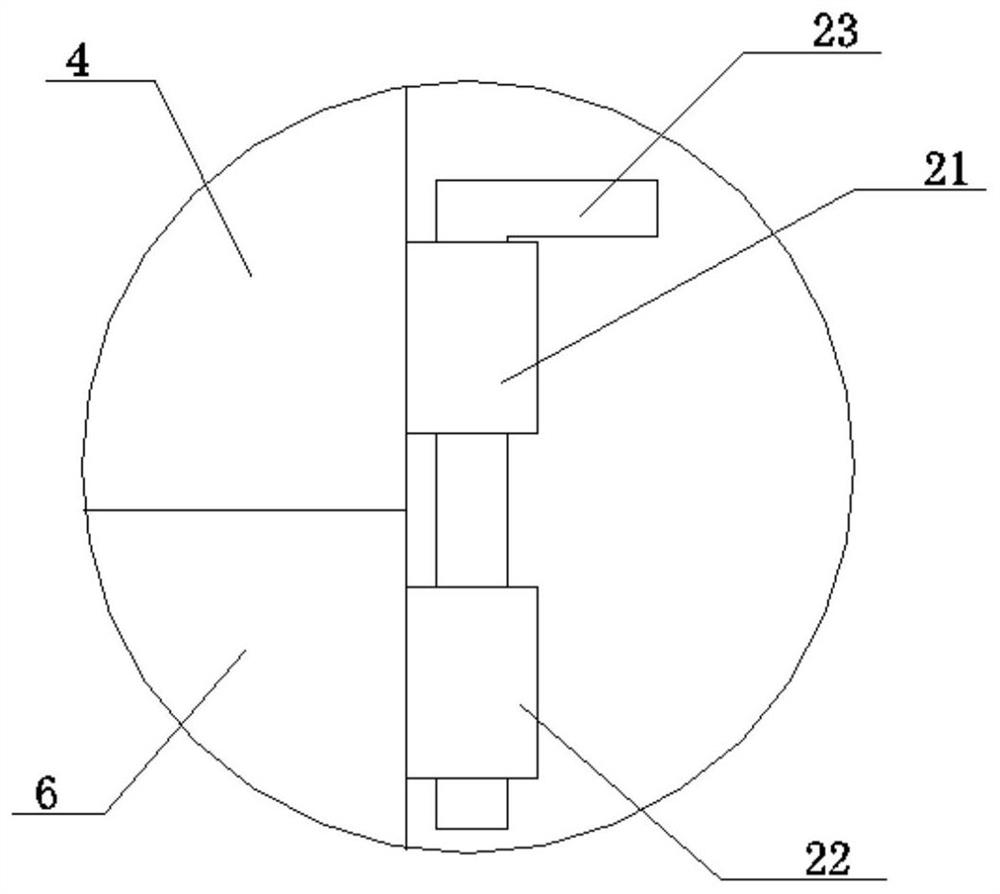
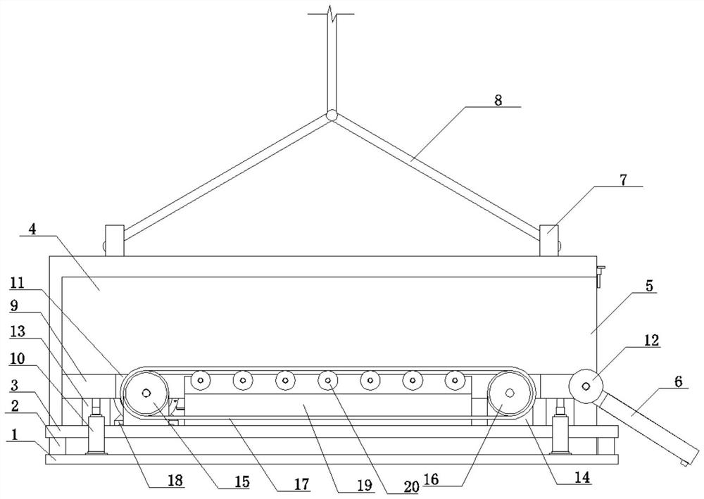
[0030] The high-altitude hoisting and quick release device for generators includes a base 1, the upper end of the base 1 is fixedly connected with a fixed seat 3 through a bracket 2, the upper end of the fixed seat 3 is provided with a supporting component and a transmission component, and the upper surface of the base 1 is fixedly connected with a frame body 4 One end of the frame body 4 is provided with an opening 5, and the opening 5 is rotatably connected with a baffle plate 6, and the upper end of the frame body 4 is fixedly connected with four suspension rings 7, and the suspension ring 7 is connected with a drag cable 8; one part of the frame body 4 The side is fixedly connected with a fixed sleeve 21, and the top of the outer wall of the baffle plate 6 is fixedly connected with a fixed sleeve 22, and a fixed pin 23 runs through between the fixed sleeve 1 21 and the fixed sleeve 22; To the fixing effect, when the frame body 4 is lifted by the drag cable 8, the frame body...

specific Embodiment approach

[0035] 1. Pull the fixing pin 23 out of the fixing sleeve 22, put down the baffle plate 6, and drive the hydraulic cylinder 10 to drive the support seat 9 to rise above the top of the conveyor belt 17;

[0036] 2. Push the generator onto the support base 9 through the baffle 6, close the baffle 6, and put down the fixing pin 23 to fix the baffle 6;

[0037] 3. Connect the cable 8 to the suspension ring 7, and drive the cable 8 to lift the frame 4 through the crane to lift the generator;

[0038] 4. After lifting the generator to the designated position, pull out the fixed pin 23, put down the baffle plate 6, start the motor 18, the motor 18 drives the driving pulley 15 to rotate, and the driving pulley 15 drives the driven pulley 16 through the conveyor belt 17, The generator is transported to the opening 5 through the conveyor belt 17, the generator enters above the baffle 6 through the guide roller 12, and slides down to the transportation place through the baffle 6.


PUM


Abstract

The invention relates to the technical field of generator hoisting, in particular to a high-altitude hoisting and quick release device for a generator. The device comprises a base; a fixed seat is fixedly connected to the upper end of the base through a support; a supporting assembly and a conveying assembly are arranged at the upper end of the fixed seat; a frame body is fixedly connected to theupper surface of the base, and an opening is formed in one side end of the frame body and the opening is rotatably connected with a baffle; and four lifting rings are fixedly connected to the upper end of the frame body, and inhaul cables are connected to the lifting rings. By arranging the conveying assembly, the generator can be conveyed, when the generator is hoisted, the generator can be conveniently and rapidly assembled and disassembled in a hoisting device, the generator and the hoisting device can be conveniently assembled and disassembled, the hoisting efficiency of the generator is improved, the generator does not need to be carried manually, and the labor intensity of workers is reduced; and the supporting assembly can play a role in supporting the generator, and when the conveying assembly conveys the generator into the frame body, a hydraulic cylinder lifts a supporting seat, so that the generator can be separated from a conveying belt to fix the generator, and meanwhile,the conveying belt can be protected during hoisting.

Description

technical field [0001] The invention relates to the technical field of generator hoisting, in particular to a high-altitude hoisting and quick release device for generators. Background technique [0002] The smooth hoisting of the generator stator of the thermal power plant unit is the basis and key for the power plant unit to be put into operation and generate electricity. In the prior art, it is generally to utilize two 80-ton cranes provided in the main workshop of the power plant unit as the main equipment, and then cooperate with other auxiliary equipment to carry out the hoisting of the generator stator. However, only the two 80-ton cranes in the main workshop can only be used to hoist the stator less than 160 tons. For the hoisting operation of the stator of the thermal power plant with more than 160 tons, especially 300MW or more, the traditional hoisting method is A temporary hoisting frame is added to the side of the main workshop, and a track, a movable structura...

Claims


Application Information

Patent Timeline
IPC IPC(8): B66C1/12B66C1/16B65G47/44B65G23/04B65G11/12B65G11/02
CPCB66C1/122B66C1/16B65G11/023B65G11/123B65G23/04B65G47/44Y02E10/72
Inventor 杜箭南危成仁周宏彦陈江波李志凯
Owner SHANXI INSTALLATION GRP CO LTD
Why Eureka
Try Eureka