Lifting type power equipment overhauling device and using method thereof

A technology for power equipment and maintenance devices, which is applied in the direction of hoisting equipment safety devices and hoisting devices, which can solve the problems of low maintenance efficiency and low operation safety, and achieve the effect of reducing work intensity

Active Publication Date: 2020-12-04
国网福建省电力有限公司泰宁县供电公司 +1
View PDF6 Cites 6 Cited by
  • Summary
  • Abstract
  • Description
  • Claims
  • Application Information

AI Technical Summary

Problems solved by technology

[0006] The present invention provides a lifting type power equipment maintenance device and its use me

Method used


Image

  • Lifting type power equipment overhauling device and using method thereof
  • Lifting type power equipment overhauling device and using method thereof
  • Lifting type power equipment overhauling device and using method thereof

Examples


Embodiment 1

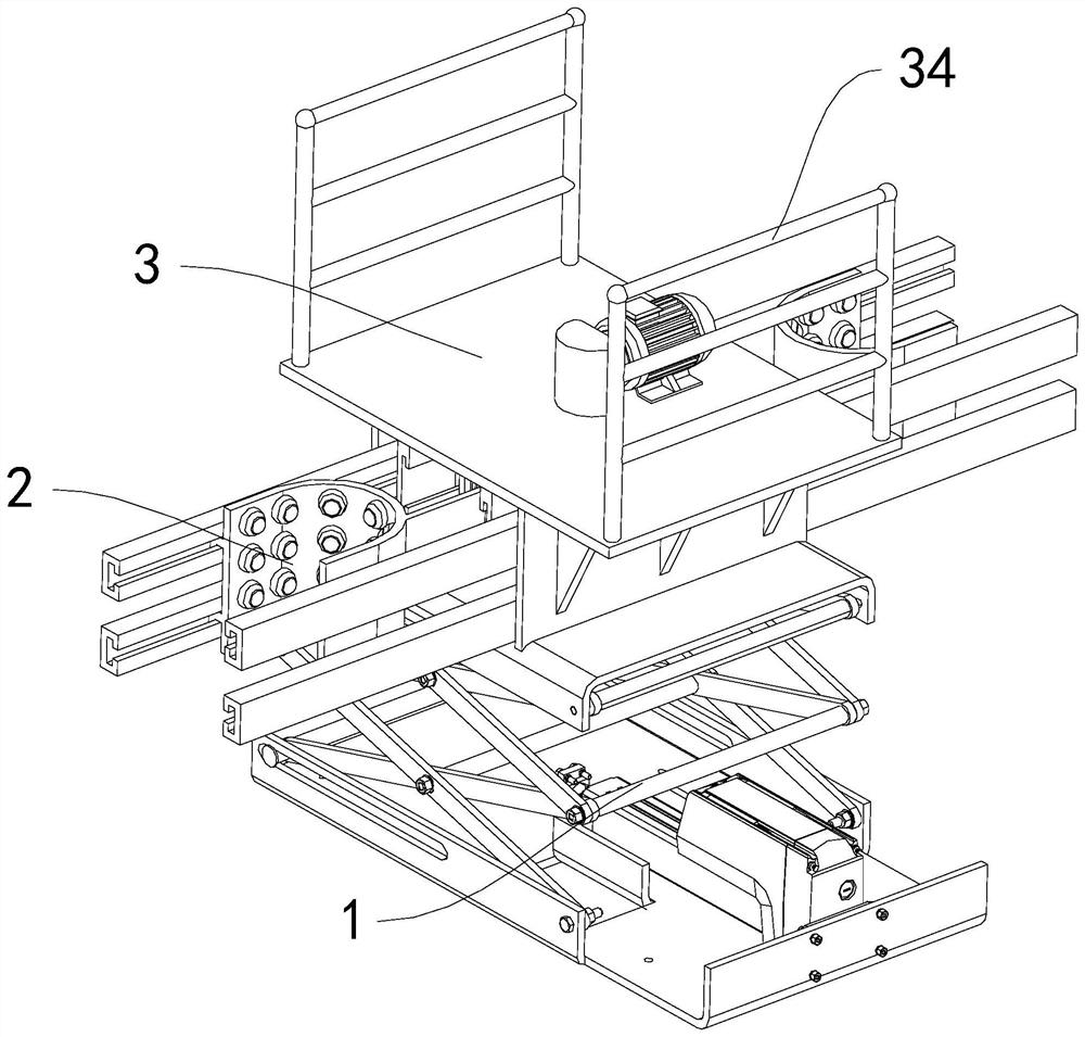
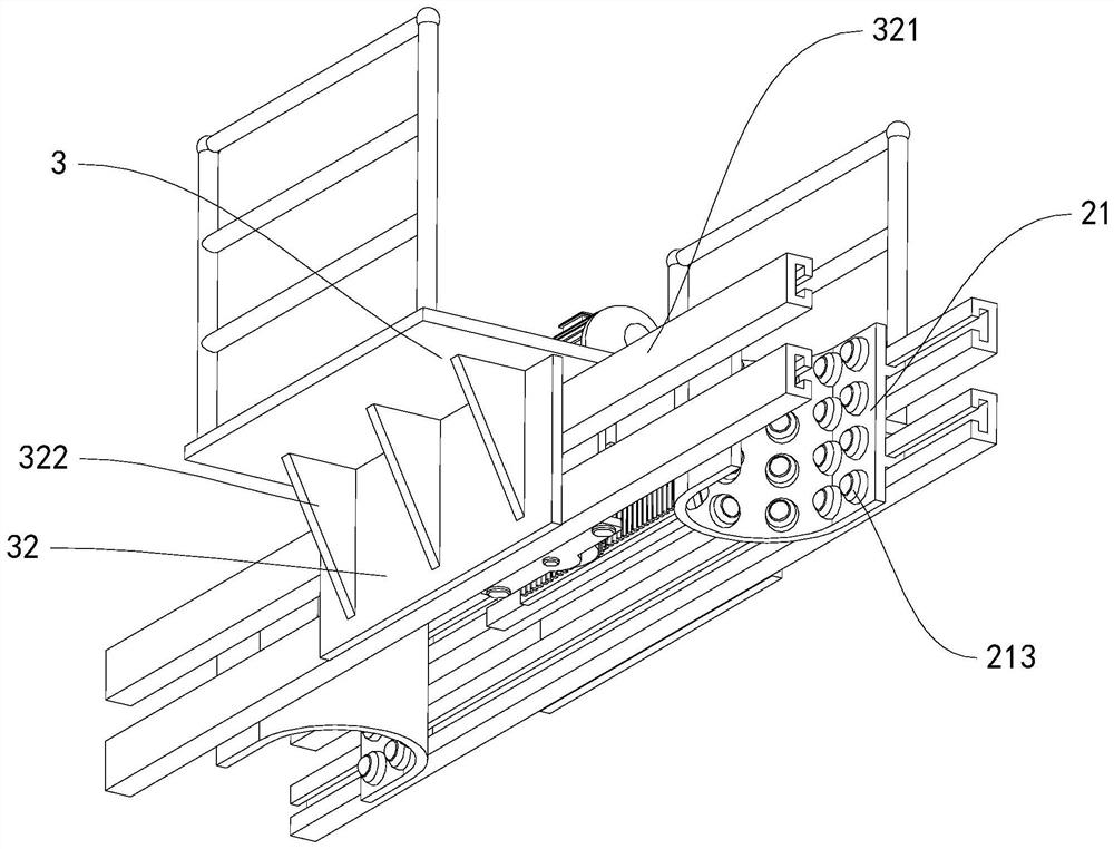
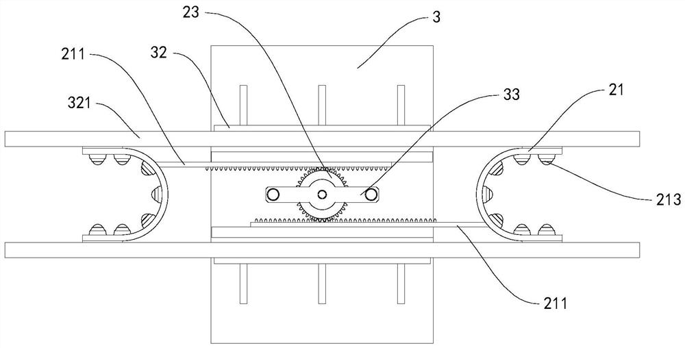
[0043] Embodiment 1: the bottom of the operating platform 3 is provided with a fixed mounting plate 32, and the fixed mounting plate 32 is provided with two, and the two fixed mounting plates 32 are symmetrically arranged on both sides of the bottom of the operating platform 3, two The opposite direction of the fixed mounting plate 32 is respectively provided with two limit chute 321, and the two outer end surfaces of the two U-shaped limit grooves 21 are respectively provided with two limit slides 212, which are located in the U-shaped position. The limit sliders 212 on both sides of the U-shaped limit groove 21 are respectively limited to the two limit chute 321, and the moving direction of the U-shaped limit groove 21 on both sides can be limited by the set limit chute 321 , so that the connection strength between the limiting device 2 and the operating platform 3 can be increased, and the limiting stability of the limiting device 2 can be improved.

Embodiment 2

[0044] Embodiment 2: The limiting chute 321 is composed of a middle fixing plate 41, a side folding plate 42, a hydraulic cylinder fixing plate 43 and a folding hydraulic cylinder 44, and the middle fixing plate 41 is installed on the fixed mounting plate 32, There are four side end folding plates 42, and the four side end folding plates 42 are connected to both sides of the two middle fixing plates 41 respectively, and the side end folding plates 42 can be carried out on the middle fixing plate 41. Folding toward the outer end direction, the hydraulic cylinder fixing plates 43 are provided with two and are respectively vertically fixed on the two fixed mounting plates 32, the folding hydraulic cylinders 44 are provided with four, and the four folding hydraulic cylinders One end of 44 is respectively connected to the two ends of the two hydraulic cylinder fixing plates 43, and the other ends of the four folding hydraulic cylinders 44 are respectively connected to the four side ...


PUM


Abstract

The invention discloses a lifting type power equipment maintenance device and a using method thereof. The lifting type power equipment maintenance device comprises a lifting device, a limiting deviceand an operation platform, wherein the operation platform is installed on the limiting device, the lifting device is installed at the bottom of the limiting device, the limiting device is composed ofU-shaped limiting grooves, a limiting motor and a limiting gear shaft, the number of the U-shaped limiting grooves is two, the two U-shaped limiting grooves each are provided with a stretching rack, two rack limiting pieces are symmetrically arranged at the bottom of the operation platform, openings of the two U-shaped limiting grooves are reversely formed in the operation platform, the stretchingracks on the two U-shaped limiting grooves are located on the two rack limiting pieces, the output end of the limiting motor is vertically arranged downwards, the limiting gear shaft is arranged between the two stretching racks and is in transmission connection with the limiting motor, and the limiting gear shaft is engaged with the two stretching racks. According to the lifting type power equipment overhauling device and the using method thereof, an operator can carry out maintenance operation on transformer equipment conveniently.

Description

technical field [0001] The invention relates to the technical field of electric power maintenance equipment, in particular to a lifting type power equipment maintenance device and a usage method based on the device. Background technique [0002] A transformer is a static electrical device used to convert AC voltage and current to transmit AC power. It is based on the principle of electromagnetic induction to achieve electrical energy transfer. Transformers can be divided into power transformers, test transformers, instrument transformers and special-purpose transformers in terms of their uses: power transformers are necessary equipment for power transmission and distribution, and power user distribution; test transformers can withstand voltage (boost) for electrical equipment Test equipment; instrument transformers are used for electrical measurement and relay protection of power distribution systems (PT, CT); special-purpose transformers include electric furnace transforme...

Claims


Application Information

Patent Timeline
IPC IPC(8): B66F11/04B66F17/00
CPCB66F11/042B66F17/006
Inventor 裘张军顾瑞升
Owner 国网福建省电力有限公司泰宁县供电公司
Why Eureka
Try Eureka