Cone sintering device in optical fiber preform powder preparation and working method

An optical fiber preform and sintering device technology, which is applied to manufacturing tools, glass manufacturing equipment, etc., can solve the problems of frequent tempering, short service life of the device, and lack of disassembly and maintenance, and achieves the effect of improving the adequacy.

Pending Publication Date: 2020-12-04
QINGHAI ZHONGLI OPTICAL FIBER TECH CO LTD
View PDF6 Cites 0 Cited by
  • Summary
  • Abstract
  • Description
  • Claims
  • Application Information

AI Technical Summary

Problems solved by technology

[0004] Aiming at the deficiencies of the prior art, the present invention provides a taper sintering device in the preparation of optical fiber preform powder body, which has the structural design of multi-layer nested combination, detachability, and the combustion interface of combustion gas and combustion-supporting gas. The advantages of uniform mixing, the

Method used


Image

  • Cone sintering device in optical fiber preform powder preparation and working method
  • Cone sintering device in optical fiber preform powder preparation and working method
  • Cone sintering device in optical fiber preform powder preparation and working method

Examples


Embodiment 1

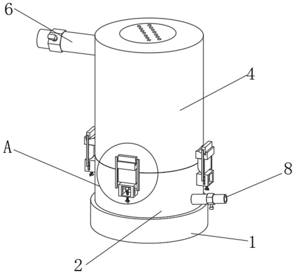
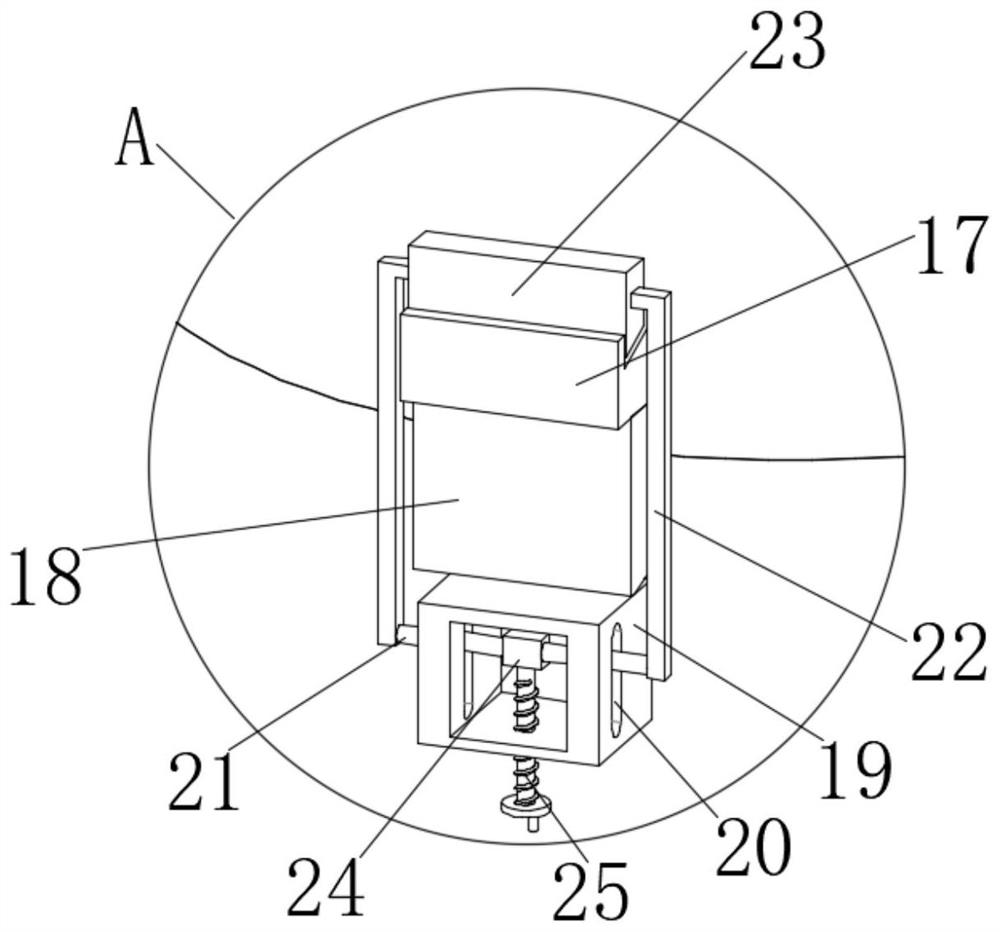
[0024] Please refer to the attached Figure 1-4 , a taper sintering device in the preparation of optical fiber preform powder, comprising a first layer of cylinder 1, a second layer of cylinder 2 and a third layer of cylinder 4, the first layer of cylinder 1 is located in the second layer of cylinder 2, the second layer of cylinder body 2 is located below the third layer of cylinder body 4, the bottom surface of the first layer of cylinder body 1 is provided with a limiting groove 5, and the limiting groove 5 is provided with hexagon socket bolt holes 3 socket bolt holes 3 At the same time, it vertically penetrates the side wall of the first layer of cylinder body 1 and the side wall of the second layer of cylinder body 2 and extends into the side wall of the third layer of cylinder body 4. The number of hexagon socket bolt holes 3 is six, and the number of The bottom end of the outer wall of the three-layer cylinder body 4 is fixedly connected with the limit block 17, and the...

Embodiment 2

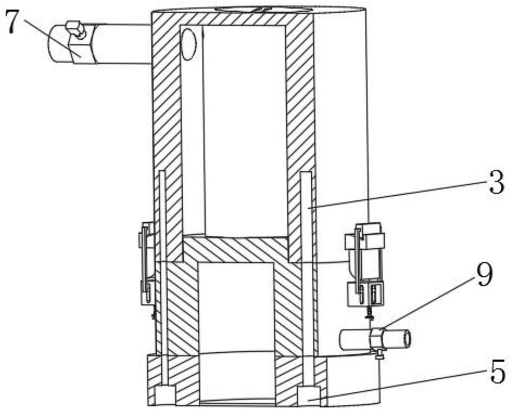
[0026] Based on Example 1, as attached Figure 1-4 , the third layer of cylinder body 4 is socketed on the surface of the second layer of cylinder body 2, a combustion-supporting gas chamber 10 is formed between the second layer of cylinder body 2 and the third layer of cylinder body 4, and the inside of the second layer of cylinder body 2 is gas Mixing chamber 12, the top wall of the second layer cylinder 2 is provided with several through holes 11, the through holes 11 run through the top wall of the second layer cylinder 2 and communicate with the combustion-supporting gas chamber 10, and the top of the gas mixing chamber 12 is opened There are several through holes 14, and the outer wall of the third layer cylinder body 4 is fixedly connected with a gas delivery pipe 16, which runs through the side wall of the third layer cylinder body 4 and communicates with the combustion-supporting gas cavity 10, and the gas delivery pipe 16 is on the A metering valve 17 is fixedly inst...


PUM


Abstract

The invention relates to the technical field of optical fiber preforms, and discloses a cone sintering device in optical fiber preform powder preparation and a working method thereof. The cone sintering device comprises a first-layer barrel, a second-layer barrel and a third-layer barrel; the first-layer barrel is located below the second-layer barrel; the second-layer barrel is located below thethird-layer barrel; and a limiting groove is formed in the bottom surface of the first-layer barrel. According to the cone sintering device in optical fiber preform powder preparation, hexagon socketscrew holes are formed and penetrate through the side wall of the first-layer barrel and the side wall of the second-layer barrel to extend into the side wall of the third-layer barrel, and the cone sintering device is designed in a multi-layer nested combination mode; the first-layer barrel, the second-layer barrel and the third-layer barrel are fixedly connected by inserting hexagon socket screws into the hexagon socket screw holes; when the hexagon socket screws are detached, the second-layer barrel and the third-layer barrel are fixedly connected through buckling connection of limiting blocks and clamping blocks, and the structural design that the device can be disassembled for maintenance is achieved.

Description

technical field [0001] The invention relates to the technical field of optical fiber preform rods, in particular to a cone portion sintering device and working method in the preparation of optical fiber preform rod powder bodies. Background technique [0002] The preparation and processing of optical fiber preform is the source and one of the most important steps of the entire optical fiber and cable production, because the manufacturing process of optical fiber preform affects the subsequent preparation of optical fiber. The core-clad ratio of the rod is consistent with the qualified optical fiber, and the time for forming the optical fiber preform fusion cone is shortened. It is necessary to pre-prepare a streamlined cone head at the drawing end of the optical fiber preform. [0003] The taper sintering device of the existing optical fiber preform inlet device is integrally welded, and the device does not have the ability to be disassembled and maintained, frequently flash...

Claims


Application Information

Patent Timeline
IPC IPC(8): C03B37/012
CPCC03B37/01251C03B37/01257
Inventor 窦生孝宋建鹏张国胜韩永春蔡福鑫马晓光王继佩
Owner QINGHAI ZHONGLI OPTICAL FIBER TECH CO LTD
Why Eureka
Try Eureka