Rapid construction method of continuous rigid frame bridge

A construction method and rigid-frame bridge technology, applied in bridges, bridge construction, erection/assembly of bridges, etc., can solve the problems of increasing the size of the lower structure and the amount of steel bars, increasing the amount of materials, and increasing construction costs, so as to reduce the amount of materials and Construction cost, improved stress state, and cost-saving effect

Inactive Publication Date: 2020-12-04
HENAN PROVINCIAL COMM PLANNING & DESIGN INST CO LTD
View PDF4 Cites 4 Cited by
  • Summary
  • Abstract
  • Description
  • Claims
  • Application Information

AI Technical Summary

Problems solved by technology

When using this method of construction, in order to resist the unbalanced force of the pier column during the construction period, the size of the substructure and the amount of steel bars must be increased, which increases the amount of materials and increases the construction cost; secondly, it takes a certain amount of time for the wet joint concrete to reach the design strength During this period, the bridge erecting machine can only stop and wait, which delays the construction progress; thirdly, when the substructure adopts traditional pile groups with caps, it is necessary to construct multiple boreholes, prepare steel sheet piles for the construction of caps, etc., and conduct underground construction. There will be problems of avoidance of urban underground pipelines, and ground construction needs to build fences to occupy a large construction land, resulting in extended construction period and increased cost

Method used


Image

  • Rapid construction method of continuous rigid frame bridge
  • Rapid construction method of continuous rigid frame bridge
  • Rapid construction method of continuous rigid frame bridge

Examples


Embodiment Construction

[0041] The embodiments of the present invention are described in detail below in conjunction with the accompanying drawings. This embodiment is implemented on the premise of the technical solution of the present invention, and detailed implementation methods and specific construction processes are provided, but the scope of protection of the present invention is not limited to the following Described embodiment.

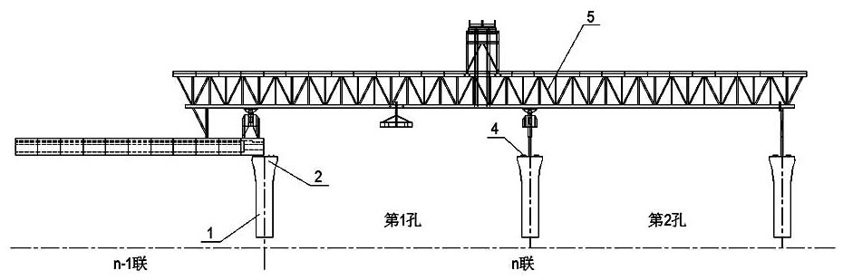
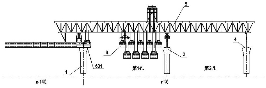
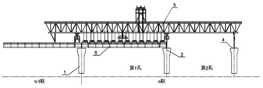
[0042] Such as Figure 1-15 Shown, the rapid construction method of continuous rigid frame bridge of the present invention, comprises the steps:

[0043] The first step is to construct the bridge substructure of the single-pile and single-column structure including the pile foundation 1 and the pier 2. Specifically, after the drilling is completed, the pile foundation reinforcement cage bound in the steel bar processing plant will be lowered to the design position. Pour concrete to complete the construction of pile foundation 1. The steel skeleton and formwork of t...


PUM


Abstract

The invention discloses a rapid construction method of a continuous rigid frame bridge, which comprises the following steps of: (1) constructing a bridge lower substructure, (2) moving a bridge erecting machine, temporarily anchoring supporting legs of the bridge erecting machine at the pier top of a pier, and sequentially hoisting all prefabricated girder sections in the ith span according to a segmental girder assembly sequence, staggering the prefabricated girder sections up and down in close rows and hang the prefabricated girder sections in an assembly preparation area on the right side of the i-th span, (3) installing a first prefabricated girder section; (4) installing subsequent girder sections; (5) assembling a whole-span segmental beam; (6) tensioning a positive bending moment beam in beam bottom plates of the prefabricated girder sections; (7) completing the construction of a next span segmental beam, and casting a pier top wet connection seam, (8) completing the construction of other spans of the coupled beam bridge; (9) tensioning the hogging moment beam in the beam top plate of the precast beam section in the coupled beam bridge; and (10) completing the construction of other coupled beams of the beam bridge. According to the method, through the processes of whole-hole segment assembling, pier top secondary pouring and the like, the material consumption and the construction cost are reduced; and prestressed tendons are stretched after the secondary pouring of the pier top is completed, the waiting time of the bridge erecting machine is shortened, and the construction progress is accelerated.

Description

technical field [0001] The invention relates to the technical field of bridge erection construction, in particular to a rapid construction method for a continuous rigid frame bridge. Background technique [0002] The continuous rigid frame bridge is a continuous girder bridge with continuous main girder and consolidated piers and girders. It does not have expansion joints and has good driving smoothness; it does not have supports, which fully avoids the damage or aging of the supports and reduces the need for later stages. Maintenance amount; the pier-beam consolidation structure adopted significantly reduces the positive mid-span bending moment, while keeping the pier top negative bending moment basically unchanged, so the unloading effect on the mid-span section of the beam is greater, which in turn can be achieved compared with continuous beams The bridge has a larger span, so it has become the preferred bridge type for long-span prestressed concrete bridges. [0003] Co...

Claims


Application Information

Patent Timeline
Patent Type & Authority Applications(China)
IPC IPC(8): E01D21/00
CPCE01D21/00
Inventor 邓翔张亚昕杨阳丁宁张留魁陈艳阳吴圣陶马振华王金涛韩丽丽汤要张朋举郭孝坤李行杨抑非常海远
Owner HENAN PROVINCIAL COMM PLANNING & DESIGN INST CO LTD
Why Eureka
Try Eureka