
Leakage-free high-pressure common-rail electronic control fuel injector assembly
A high-pressure common rail and electronically controlled fuel injection technology, which is applied in the direction of machines/engines, fuel injection devices, special fuel injection devices, etc. Solve problems such as large oil return, achieve good power performance, increase effective power, and reduce fuel consumption
- Summary
- Abstract
- Description
- Claims
- Application Information
AI Technical Summary
Problems solved by technology
Method used
Image

Examples
Embodiment
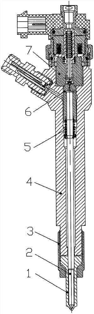
[0016] Please refer to the accompanying drawings of the specification. In the embodiment of the present invention, a non-leakage high-pressure common rail electronically controlled fuel injector assembly includes a fuel injector assembly, a control valve assembly, and a fuel injector body 4;
[0017] The injector assembly includes a needle valve body 1 and a needle valve 2, the needle valve 2 is an elongated integral structure, and the lower end of the needle valve 2 is installed in the inner cavity of the needle valve body 1;
[0018] The control valve assembly includes a nozzle assembly and a control valve seat 6. A tight cap 3 is provided at the lower end of the injector body 4, and the needle valve body 1 is locked on the injector through the tight cap 3. On the injector body 4, the control valve seat 6 is arranged on the upper end of the needle valve 2, and the upper end of the injector body 4 is provided with a compression nut 7, and the upper end of the control valve sea...
PUM
 Abstract
Description
Claims
Application Information