Multi-working-condition simulated aircraft wire harness abrasion experiment equipment and experiment method
A technology of experimental equipment and experimental methods, which is applied in the field of aircraft harness wear test equipment for multi-working condition simulation, can solve problems such as narrow cabin space, reduced service life of wire harness, signal transmission quality, wear and tear between aircraft wire harness and structure, and achieve stable movement , the effect of easy installation
- Summary
- Abstract
- Description
- Claims
- Application Information
AI Technical Summary
Problems solved by technology
Method used
Image

Examples
Embodiment 1
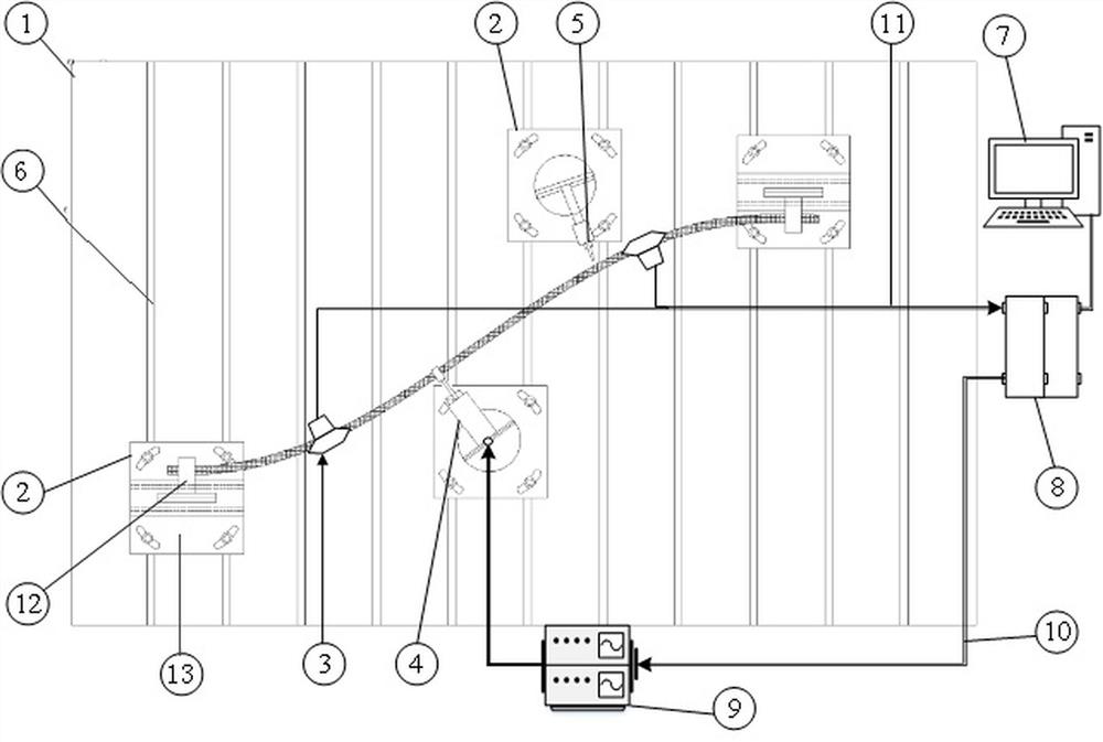
[0045] As a basic embodiment of the present invention, the present invention includes a multi-working-condition simulation aircraft harness wear test equipment, including a test bench 1, a signal acquisition device, two clamping devices 2 and an excitation device. The clamping device 2 is hinged with a vertical plate 14 , and the vertical plate 14 is connected with a fixing piece for fixing the aircraft wire harness or the wire harness wear test object, and the fixing piece can be a wire harness clamp 12 . The wire harness wear test object may be a wire harness, and the aircraft wire harness and the two ends of the wire harness are respectively fixed on the vertical plate 14 through the wire harness clamp 12 . The aircraft wire harness and the wire harness are simultaneously fixed by the two clamping devices 2 , and the distance between the aircraft wire harness and the wire harness can be adjusted by adjusting the wire harness clip 12 .
[0046] The vibration excitation devic...
Embodiment 2
[0049] As a preferred embodiment of the present invention, the present invention includes a multi-working-condition simulation aircraft harness wear test equipment, including a test bench 1, a signal acquisition device, three clamping devices 2 and two vibration excitation devices. Two of the clamping devices 2 are hinged with a vertical plate 14, and the vertical plate 14 is connected with a wire harness clamp 12 for fixing the aircraft wiring harness, so that the two clamping devices 2 are respectively located at two ends of the aircraft wiring harness. The vertical plate 14 on the other clamping device 2 is connected with a test piece chuck 5 for fixing the test object of wire harness abrasion. The aircraft wire harness and the wire harness wear test object are fixed separately to facilitate the adjustment of the distance between them.
[0050] The test bench 1 is provided with a number of evenly spaced chutes, and the lower surface of the clamping device 2 and the mounting...
Embodiment 3
[0054] As the best implementation mode of the present invention, with reference to the attached figure 1 , The present invention includes a multi-working condition simulation aircraft harness wear test equipment, including a test bench 1, a signal acquisition device, four clamping devices 2 and two excitation devices. The test bench 1 is provided with a plurality of sliders 6 , and the sliders 6 are evenly arranged along the length direction of the test bench 1 , and the sliders 6 run through the width direction of the test bench 1 .
[0055] The clamping device 2 includes an installation base plate 13 and a vertical plate 14 hinged on the installation base plate 13, and four base plate installation holes for matching with bolts are provided around the installation base plate 13. The vertical plates 14 on the two clamping devices 2 are connected with a fixing part for fixing the aircraft wiring harness, which can be a wire harness clamp 12; the vertical plates 14 on the other ...
PUM
 Abstract
Description
Claims
Application Information
 - R&D
- Intellectual Property
- Life Sciences
- Materials
- Tech Scout
- Unparalleled Data Quality
- Higher Quality Content
- 60% Fewer Hallucinations
Browse by: Latest US Patents, China's latest patents, Technical Efficacy Thesaurus, Application Domain, Technology Topic, Popular Technical Reports.
© 2025 PatSnap. All rights reserved.Legal|Privacy policy|Modern Slavery Act Transparency Statement|Sitemap|About US| Contact US: help@patsnap.com