
MMC power module thyristor overvoltage bypass test loop and test method

A test circuit and power module technology, which is applied in the electric power field, can solve the problems of undisclosed bypass thyristors and low current, and achieve the effect of improving long-term operation reliability

Inactive Publication Date: 2020-12-04
EXAMING & EXPERIMENTAL CENT OF ULTRAHIGH VOLTAGE POWER TRANSMISSION COMPANY CHINA SOUTHEN POWER GRID
View PDF8 Cites 6 Cited by
  • Summary
  • Abstract
  • Description
  • Claims
  • Application Information

AI Technical Summary

Problems solved by technology

However, in the actual working condition of the start-up phase of the flexible DC transmission system, the current is small, and the test method for whether the bypass thyristor can break down and realize the reliable bypass of the power module has not been made public.

Method used


Image

  • MMC power module thyristor overvoltage bypass test loop and test method
  • MMC power module thyristor overvoltage bypass test loop and test method

Examples


Embodiment 1

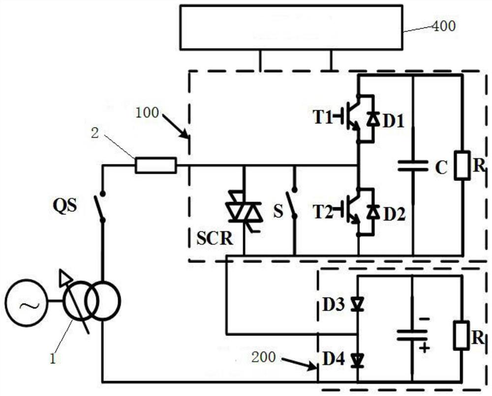
[0048] refer to figure 1 As shown, the test circuit provided in this embodiment includes a voltage regulator 1 , a vacuum switch QS, a series resistor 2 and an accompanying test module 200 .

[0049] Wherein, the voltage regulator 1 is used to be connected to a power supply, and the output terminal is connected in series with a series resistor 2 and used to be connected to the accompanying test module 200 and the half-bridge power module 100 under test. Small, about 3A, to simulate the working condition of the soft DC converter valve starting and charging in the actual project; the vacuum switch QS is set on the line between the output terminal of the voltage regulator 1 and the series resistor 2; the accompanying test module uses In order to make the forward and reverse currents of the half-bridge power module under test the same size, if there is no accompanying test module, the reverse current is greater than the forward current (charging the capacitor in the forward direct...

Embodiment 2

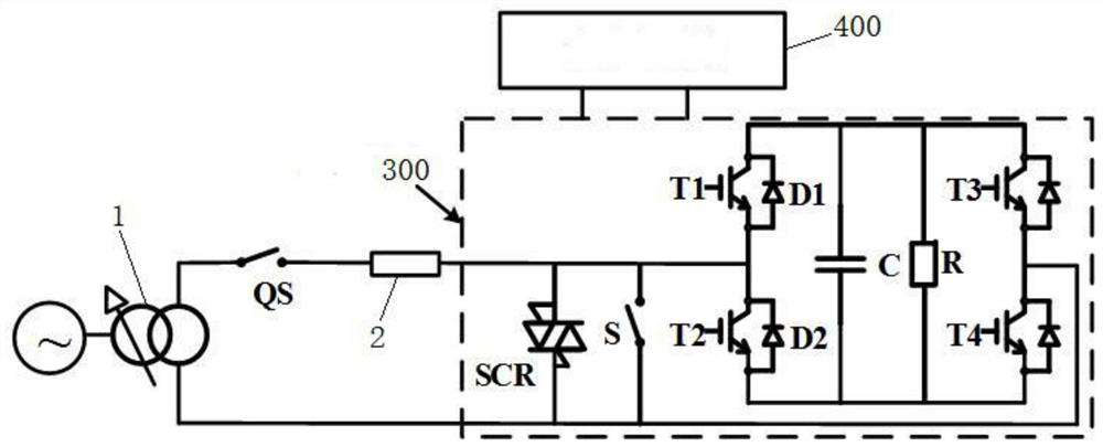
[0064] refer to figure 2 As shown, the test circuit provided in this embodiment includes a voltage regulator 1 , a vacuum switch QS and a series resistor 2 .

[0065] Wherein, the voltage regulator 1 is used to be connected to a power supply, and the output terminal is connected in series with a series resistor 2 and used to be connected to the full-bridge power module 300 under test; the vacuum switch QS is set at the output terminal of the voltage regulator 1 and connected to the series resistor 2 on the line between.

[0066] For the small current overvoltage thyristor bypass test of the full bridge power module, the test principle diagram is as follows figure 2 As shown, the preparation before the test:

[0067] (1) According to figure 2 The shown test topology connects the test circuit, including the circuit and the cooling water circuit 400. The cooling water circuit 400 is an existing conventional technology. The water circuit is used to dissipate heat for the IGB...


PUM


Abstract

The invention discloses a test loop and an MMC power module thyristor overvoltage bypass test loop and a test method in a flexible DC power transmission small current starting stage. The test loop comprises a voltage regulator, a switch, a series resistor and a test accompanying module. The voltage regulator is used for being connected with a power supply, and the output end of the voltage regulator is connected with the series resistor in series and used for being connected with the test accompanying module and a tested half-bridge power module. The switch is arranged on a circuit between theoutput end of the voltage regulator and the series resistor; and the test accompanying module is used for enabling forward and reverse currents of the tested half-bridge power module to be consistentin size. The test method can simulate the working condition that the bypass switch refuses to operate in the small current starting charging stage in the actual engineering of the flexible direct current transmission system, and can judge whether the designed power module bypass thyristor can enable the power module to bypass reliably under the working condition or not.

Description

technical field [0001] The invention relates to the field of electric power technology, in particular to a test circuit and a thyristor overvoltage bypass test method of an MMC power module in the small current start-up stage of flexible direct current transmission. Background technique [0002] With the breakthrough of high-power IGBT device technology, the improvement of product yield and the reduction of production cost, ultra-(ultra) high-voltage flexible DC transmission has been applied to power transmission projects. Modular multilevel converters (MMC) use power modules as As the smallest unit of commutation, a high-voltage flexible DC transmission converter valve consists of hundreds or thousands of power modules. Usually, each converter valve is equipped with a certain number of redundant power modules. When a power module fails, the Module bypass, as long as the number of bypass power modules is within the redundant number, the HVDC flexible transmission system can ...

Claims


Application Information

Patent Timeline
Patent Type & Authority Applications(China)
IPC IPC(8): G01R31/26
CPCG01R31/2601G01R31/263
Inventor 邹延生陈晓鹏胡雨龙周竞宇王振梁宁肖凯国建宝杨光源
Owner EXAMING & EXPERIMENTAL CENT OF ULTRAHIGH VOLTAGE POWER TRANSMISSION COMPANY CHINA SOUTHEN POWER GRID
Learn More