High-voltage power distribution cabinet assembling equipment and assembling method thereof

A technology for high-voltage power distribution cabinets and assembly equipment, applied in metal processing equipment, chemical instruments and methods, cleaning methods and appliances, etc., can solve problems such as inability to assemble cabinets and cover plates, and inability to change the inclination angle of punching holes, etc., to achieve Stabilize the limit and positioning, improve the effect of accuracy

Inactive Publication Date: 2020-12-04
苏太中
View PDF1 Cites 9 Cited by
  • Summary
  • Abstract
  • Description
  • Claims
  • Application Information

AI Technical Summary

Problems solved by technology

[0007] The purpose of the present invention is to provide a high-voltage power distribution cabinet assembly equipment and its assembly method to solve the problems in the prior art that the cabinet body and the cover plate cannot be quickly assembled and the inclination angle of the punching hole cannot be changed during the punching process. technical problem

Method used


Image

  • High-voltage power distribution cabinet assembling equipment and assembling method thereof
  • High-voltage power distribution cabinet assembling equipment and assembling method thereof
  • High-voltage power distribution cabinet assembling equipment and assembling method thereof

Examples


Embodiment Construction

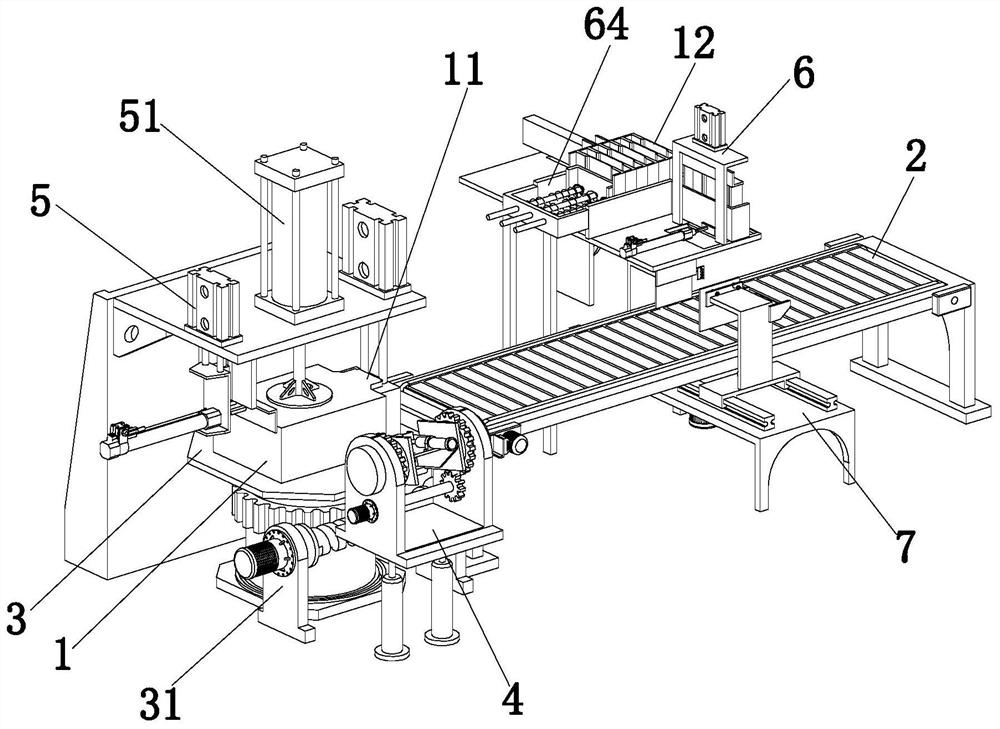
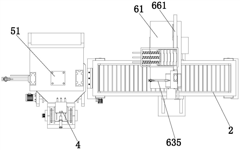
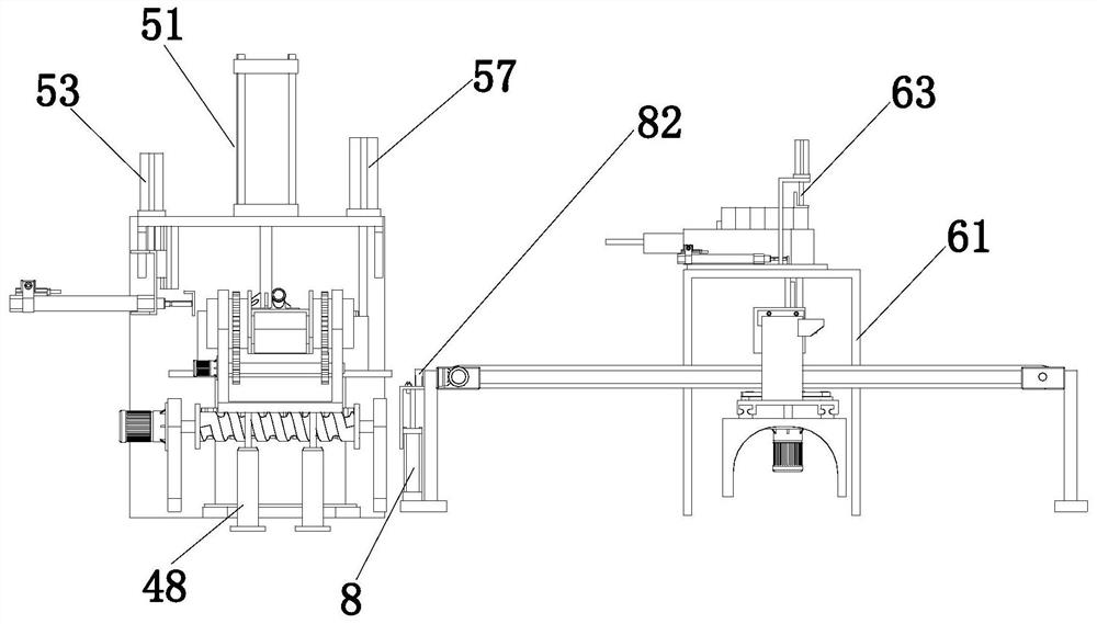
[0069] The following will be combined with Figure 1 to Figure 9 The present invention is described in detail, and the technical solutions in the embodiments of the present invention are clearly and completely described. Apparently, the described embodiments are only some of the embodiments of the present invention, not all of them. Based on the embodiments of the present invention, all other embodiments obtained by persons of ordinary skill in the art without making creative efforts belong to the protection scope of the present invention.

[0070] The present invention provides a high-voltage power distribution cabinet assembly equipment and its assembly method through improvement, such as Figure 1-Figure 9 As shown, a high-voltage power distribution cabinet assembly equipment includes a conveyor belt 2 and a bearing platform 3 horizontally arranged on the side of the conveyor belt 2, which also includes:

[0071] The inclined hole processing mechanism 4 is arranged on the ...


PUM


Abstract

The invention relates to high-voltage power distribution cabinet assembling equipment and an assembling method thereof, which belong to the technical field of high-voltage power distribution cabinet assembling equipment. The equipment comprises a conveyor belt, a bearing platform, an inclined hole processing mechanism, a rotating mechanism, a cabinet body positioning mechanism, an automatic coverplate press-fitting mechanism and a centering and righting mechanism; the automatic cover plate press-fitting mechanism comprises a supporting table, an intermittent pushing assembly, a press-fittingassembly and a storage frame arranged at the top of the supporting table, a feeding sliding way communicated with the storage frame is arranged on one side of the storage frame, a pushing strip in sliding fit with the feeding sliding way is arranged in the feeding sliding way, a through groove allowing a cover plate to pass through is formed in one side of the supporting table, and a positioning plate is arranged on the side, close to the through groove, of the supporting table. Under the action of the automatic cover plate press-fitting mechanism, the press-fitting plate pushes the top end ofthe cover plate, so that the cover plate is press-fitted on the boss of the cabinet body, the inclined hole machining mechanism conducts punching on the three side walls of the cabinet body, and theforming punching head can machine inclined holes with different inclined angles in the cabinet body.

Description

technical field [0001] The invention relates to the technical field of high-voltage power distribution cabinet assembly equipment, in particular to a high-voltage power distribution cabinet assembly equipment and an assembly method thereof. Background technique [0002] The power distribution cabinet is a widely used electrical product made of a frame structure. The power distribution cabinet is composed of a shell, internal electrical components and connecting wires. The shell of the power distribution cabinet supports and installs various electrical components and connecting wires. The shell of a general power distribution cabinet is a rectangular parallelepiped frame made of metal materials (such as angle iron, channel steel, etc.). Open and close the door, weld or fix the electrical component board with screws in the rectangular parallelepiped frame, and install various electrical components and wires on the electrical component board, with the development of the power d...

Claims


Application Information

Patent Timeline
Patent Type & Authority Applications(China)
IPC IPC(8): H02B3/00B23P19/027B21D28/24B21D28/04B08B1/00B08B5/02
CPCB08B1/002B08B5/02B21D28/04B21D28/24B23P19/027H02B3/00
Inventor 不公告发明人
Owner 苏太中
Why Eureka
Try Eureka