Method for calibrating syringe pump, syringe pump and device

A technology of syringe pumps and syringes, applied in the direction of hypodermic injection devices, medical equipment, instruments, etc.

Active Publication Date: 2020-12-04
FRESENIUS MEDICAL CARE DEUTSCHLAND GMBH
View PDF6 Cites 0 Cited by
  • Summary
  • Abstract
  • Description
  • Claims
  • Application Information

AI Technical Summary

Problems solved by technology

[0003] In order to ensure correct and precise control of the motor, the syringe pump must previously undergo a calibration process which was by far very complex

Method used


Image

  • Method for calibrating syringe pump, syringe pump and device
  • Method for calibrating syringe pump, syringe pump and device
  • Method for calibrating syringe pump, syringe pump and device

Examples


Embodiment Construction

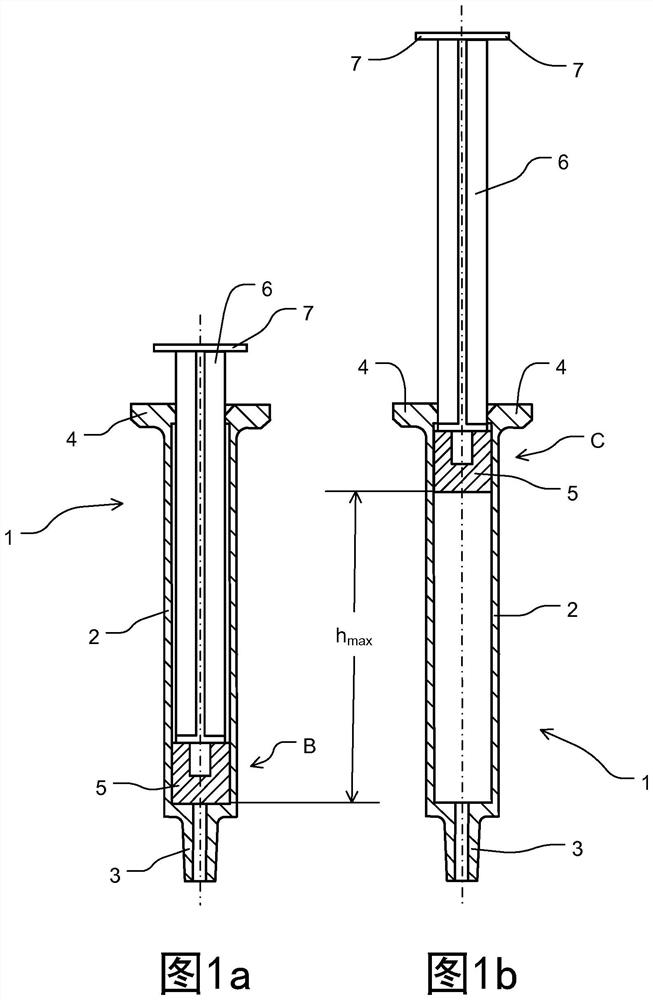
[0090] Figure 1a and Figure 1b A conventional syringe 1 , which can be a single-use syringe and / or a prefilled syringe, which can be filled with heparin, for example, is shown from the side, respectively. Figure 1a shows the syringe in its empty state, Figure 1b It is shown in its fully filled state or the state it is in when it is fully filled.

[0091] The syringe 1 comprises a syringe barrel 2 and a plunger 5 .

[0092] The syringe barrel 2 includes an optional luer cone 3 integrally formed on its head side and a syringe flange 4 formed on the opposite end.

[0093] The plunger 5 is usually made of elastomeric material and is plunger-like. A plunger 5 is located inside the syringe barrel 2 and is connected to a plunger rod 6 so that it can move axially within the syringe barrel 2 .

[0094] The end of the plunger 5 generally has an oval or circular push plate 7 when viewed from the top. exist Figure 1a and Figure 1b The push plate 7 is shown from the side.

...


PUM


Abstract

The present invention relates to a method for calibrating a medical syringe pump (100). The invention further relates to a medical syringe pump (100), which is configured and / or prepared to carry outthe method according to the invention, or which is calibrated therewith, and to a blood treatment device which has such a medical syringe pump (100) or can be connected to such a syringe pump. Furthermore, the present invention relates to a digital storage medium, a computer program product and a computer program.

Description

technical field [0001] The invention relates to a method for calibrating a medical syringe pump according to claim 1 . The invention also relates to a medical syringe pump according to claims 10 and 20 and a blood therapy device according to claim 21 . The invention also relates to a digital storage medium according to claim 23 , a computer program product according to claim 24 and a computer program according to claim 25 . Background technique [0002] Syringe pumps are known from practical experience. The associated pump control requires a signal indicative of the determined position of the linear movement of the movable or displaceable slide of the syringe pump by or through which the syringe is emptied. These signals are recorded by sensors, which may be, for example, magnetic field sensors (eg Hall sensors) or photoelectric sensors (eg light barriers). The syringe pump sensors are used in pump control to determine or detect or define the actual position of the slide ...

Claims


Application Information

Patent Timeline
Patent Type & Authority Applications(China)
IPC IPC(8): A61M5/145A61M5/142
CPCG16H20/17A61M5/142A61M5/1456A61M2205/3306A61M2205/3317A61M2205/70G01B21/042G16H40/40A61K31/7016A61M1/16A61M1/28A61M1/34A61M1/3413A61M5/1452A61M2205/502A61M2205/52G01D5/145G01D5/16G01D5/32
Inventor M·坦内贝格J·西伯特R·罗格曼P·迪茨J·吕克特
Owner FRESENIUS MEDICAL CARE DEUTSCHLAND GMBH
Why Eureka
Try Eureka