Check patentability & draft patents in minutes with Patsnap Eureka AI!

Memory controller and memory control system

A technology of memory controller and memory, which is applied in the direction of instruments, various digital computer combinations, electrical digital data processing, etc., and can solve the problems of increasing system overhead

Inactive Publication Date: 2003-09-03
KK TOSHIBA
View PDF3 Cites 0 Cited by
  • Summary
  • Abstract
  • Description
  • Claims
  • Application Information

AI Technical Summary

Problems solved by technology

However, once this operation is synchronized, subsequent operations (or operations that meet the synchronization conditions) cannot be performed until the previous operation is completed, resulting in additional system overhead during the synchronization process.

Method used


Image

  • Memory controller and memory control system
  • Memory controller and memory control system
  • Memory controller and memory control system

Examples


no. 1 example

[0088] In the following, reference will be made to Figure 3 to Figure 4 The operation of the first embodiment is briefly described.

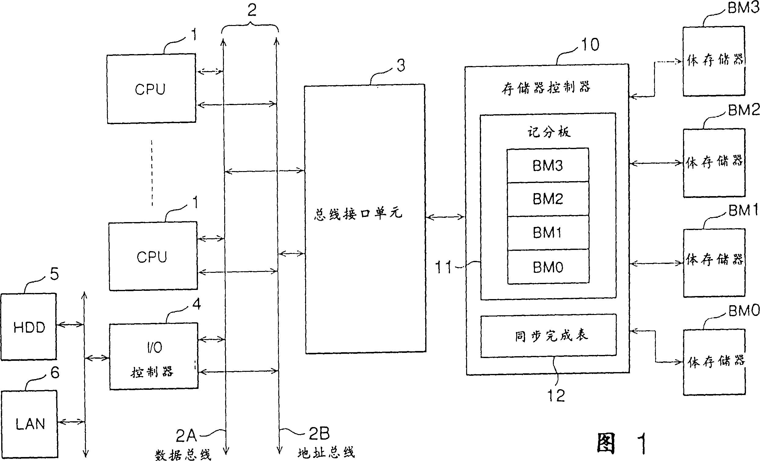
[0089]As described above, the memory controller 10 of this embodiment controls the bank memories BM0 to BM3 corresponding to the four memory areas 0 to 3 by the 4-way interleave function. The memory controller 10 shown in FIG. 3 includes execution units 108 , 118 , 128 , 138 and scoreboards 100 , 110 , 120 , 130 , which are separately provided for the four memory banks BM0 to BM3 . In the scoreboards 100, 110, 120, 130, the valid flag is represented by "Val", the issue enable flag is represented by "Fn", and the synchronization flag is represented by "SYNC".

[0090] like Figure 4 As shown, after receiving a memory access instruction from the processor bus 2, the bus interface unit 3 transmits the instruction to the memory controller 10 (step S1). When receiving a memory access command to one of the memory areas 0 to 3, the memory controller ...

no. 2 example

[0134] As shown in FIG. 17 , the second embodiment of the present invention is to add an entry 160 for synchronization conditions in the synchronization completion table 12 . The entry 160 is an item for indicating a synchronization condition related to a request from the same requester (processor) or a synchronization condition related to the same address (here, it is assumed that the condition is applied to the same address). The rest of the system structure and constitution of the memory controller 10 are the same as those of the first embodiment.

[0135] The above structure realizes the function of executing continuous instructions (continuous operation) that do not satisfy the synchronization condition and will not be affected by the synchronization operation. Among the operations satisfying the synchronization condition, operations performed after the synchronization operation are prohibited from being performed earlier than operations performed before the synchronizati...

no. 3 example

[0168] The third embodiment of the present invention is such a system, it can simultaneously realize the processing function of a plurality of synchronous instructions and comprises a memory controller 10, this memory controller 10 has a plurality of synchronization flags (SYNC flags) provided with multilevel The scoreboard and a synchronization completion table are provided with multi-level synchronization completion markers (SYNC completion). Subsequent synchronization operations are not retried until all synchronization levels have been used.

[0169] In the third embodiment, synchronization processing is performed in the order in which synchronization operations are performed. In particular, where synchronous operations A, B, and C are received, they are executed in the following order; operations received before synchronous operation A, operations received between synchronous operations A and B, operations received between synchronous operations B and Operations received...


PUM


Abstract

A memory controller provided on a multiprocessor system has a scoreboard (11) used to manage the progress of memory access operations (the operating state of access instructions) and reduces the overhead in executing synchronization at a high level of execution priority. The scoreboard (11) holds synchronization flags set in response to the acceptance of synchronization as well as the operation codes and addresses of the accepted access instructions. The memory controller (10) sets a synchronization flag at the time when it has accepted a synchronizing instruction from the processor (1), and then resets the synchronization flag after the execution of the synchronizing operation has been completed.

Description

technical field [0001] The present invention relates to a memory controller and a memory control method for a multiprocessor system, and more particularly to a memory controller and a memory control method for synchronizing data stored using a bank method. Background technique [0002] Multiprocessor systems have been provided with tools for managing and controlling memory-bank-type shared main memory and executing access instructions in an out-of-order or weak-order manner ( memory controller including data and address). [0003] The memory controller not only has a function of individually controlling each bank memory corresponding to an individual memory area, but also has a function of temporarily replacing weak-order synchronization with strong-order synchronization. Methods related to this synchronous operation are approximately divided as follows. [0004] The first method is as follows: A buffer memory having a first-in-first-out (FIFO) function is used for address...

Claims


Application Information

Patent Timeline
Patent Type & Authority Patents(China)
IPC IPC(8): G06F13/16
CPCG06F13/1689G06F15/16
Inventor 黑泽泰彦
Owner KK TOSHIBA
Features
  • R&D
  • Intellectual Property
  • Life Sciences
  • Materials
  • Tech Scout
  • Unparalleled Data Quality
  • Higher Quality Content
  • 60% Fewer Hallucinations
Learn More