Copper-clad plate manufacturing process

A manufacturing process and copper clad laminate technology, applied in the field of copper clad laminate manufacturing process, can solve the problems of deformation of the cutting position of the copper clad laminate, uneven edges, large volume of the copper clad laminate, etc., to improve the yield rate, avoid deformation, and improve production efficiency Effect

Active Publication Date: 2020-12-08
深圳可瑞高新材料股份有限公司
View PDF4 Cites 0 Cited by
  • Summary
  • Abstract
  • Description
  • Claims
  • Application Information

AI Technical Summary

Problems solved by technology

[0003] In the manufacture of copper clad laminates, the laminated copper clad laminates after multilayer boards are often bulky, and the glue overflows around the periphery, and the edges are uneven. In this case, the laminated copper clad laminates need to be cut. However, the conventional cutting method is to manually operate the cutting device to directly cut the laminated copper clad laminate. This method is likely to cause deformation of the cutting position of the copper clad laminate during cutting, and it is easy to produce a large amount of damage at the cutting place after cutting. The burrs affect the yield rate of copper clad laminates, and the conventional cutting method is single cutting, a copper clad laminate often needs to be cut multiple times, which greatly reduces the production efficiency of copper clad laminates

Method used


Image

  • Copper-clad plate manufacturing process
  • Copper-clad plate manufacturing process
  • Copper-clad plate manufacturing process

Examples


Embodiment Construction

[0031] In order to make the technical means, creative features, objectives and effects achieved by the present invention easy to understand, the present invention will be further described below in conjunction with specific illustrations. It should be noted that, in the case of no conflict, the embodiments in the present application and the features in the embodiments can be combined with each other.

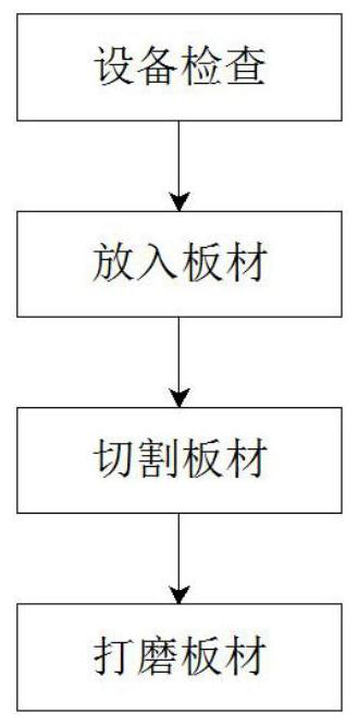
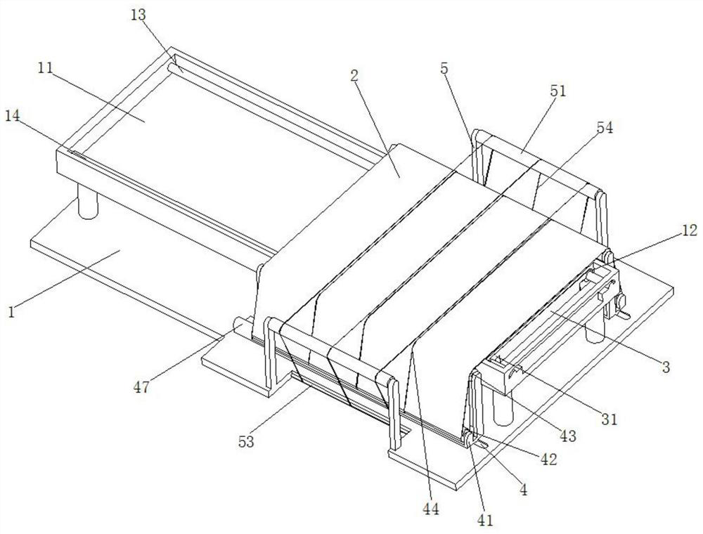
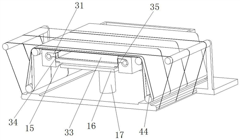
[0032] Such as Figure 1 to Figure 8 As shown, a copper clad laminate manufacturing process, which uses a copper clad laminate manufacturing device, the copper clad laminate manufacturing device includes a machine tool 1, a grinding belt 2 and a bracket 3, using the above copper clad laminate manufacturing device to manufacture the copper clad laminate specifically Methods as below:

[0033] S1. Equipment inspection: check the operation of the equipment before using the copper clad laminate manufacturing device to manufacture copper clad laminates;

[0034] S2. Putting in the ...


PUM


Abstract

The invention relates to the field of plate manufacturing, in particular to a copper-clad plate manufacturing process. According to the copper-clad plate manufacturing process, a copper-clad plate manufacturing device is in use. The copper-clad plate manufacturing device comprises a machine tool, a polishing belt and a bracket. A movable trough is fixedly installed on the top of the machine tool,and insertion grooves of arc-shaped structures are symmetrically formed in the inner wall of the movable trough. A lead screw and a guide rod are inserted into the insertion grooves respectively, a first groove of a rectangular structure is formed in the movable trough, a pressing plate is arranged in the first groove, the bracket is of a rectangular structure, insertion blocks are symmetrically and fixedly installed on the two sides of the bracket, the sides, away from the bracket, of the insertion blocks are each of an arc-shaped structure, and the insertion blocks are correspondingly connected with the insertion grooves in an inserted mode. The bottom of each insertion block makes contact with the lead screw and the guide rod respectively, threads are formed in the side, making contactwith the lead screw, of the insertion block, and a second groove is formed in the bracket. With the copper-clad plate manufacturing process, a copper-clad plate can be prevented from deforming duringcutting, and meanwhile, burrs generated during cutting can be removed, and the copper-clad plate cutting process is suitable for promotion.

Description

technical field [0001] The invention relates to the field of copper clad laminate manufacturing, in particular to a copper clad laminate manufacturing process. Background technique [0002] The full name of copper-clad laminate is copper-clad laminate, which is a kind of base material. It is made of wood pulp paper or glass fiber cloth, etc. A product, when it is used in the production of multilayer boards, it is also called a core board. [0003] In the manufacture of copper clad laminates, the laminated copper clad laminates after multilayer boards are often bulky, and the glue overflows around the periphery, and the edges are uneven. In this case, the laminated copper clad laminates need to be cut. However, the conventional cutting method is to manually operate the cutting device to directly cut the laminated copper clad laminate. This method is likely to cause deformation of the cutting position of the copper clad laminate during cutting, and it is easy to produce a lar...

Claims


Application Information

Patent Timeline
Patent Type & Authority Applications(China)
IPC IPC(8): B23P23/04B23Q3/06
CPCB23P23/04B23Q3/06
Inventor 俞烽未海
Owner 深圳可瑞高新材料股份有限公司
Why Eureka
Try Eureka