
CNC (Computer Numerical Control) machining and positioning device for template workpiece

A technology for positioning devices and workpieces, which is applied to positioning devices, metal processing equipment, metal processing machinery parts, etc., can solve problems such as reduced work efficiency, inaccurate positioning of workpieces, and substandard production quality of workpieces, so as to facilitate production quality and improve The effect of precision

Pending Publication Date: 2020-12-08
武汉普泰金属制造技术有限公司
View PDF7 Cites 2 Cited by
  • Summary
  • Abstract
  • Description
  • Claims
  • Application Information

AI Technical Summary

Problems solved by technology

[0002] Workpiece, a product part in the manufacturing process; also called workpiece, work piece, courseware, hardware piece, etc., and the workpiece can be processed by CNC processing, and CNC processing usually refers to computer digital control precision machining, CNC machining lathe , CNC processing milling machine, CNC processing boring and milling machine, etc., while CNC processing usually requires a positioning device for processing, but the existing positioning device for CNC processing of template workpieces is generally only position positioning, while template workpieces need shape positioning during processing, sometimes requiring staff Manual positioning leads to inaccurate positioning of the workpiece, the production quality of the workpiece is not up to standard, and wastes production costs. Moreover, manual assistance is required for clamping, which increases the workload of the staff and reduces work efficiency.

Method used

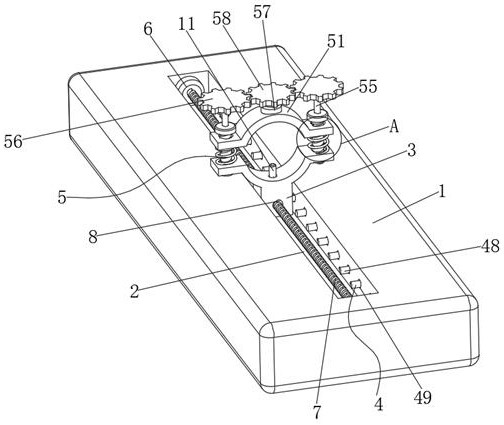
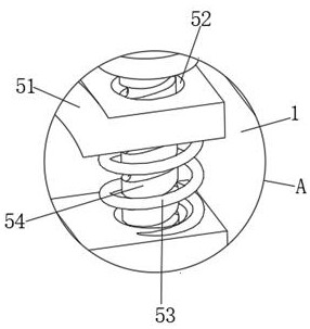
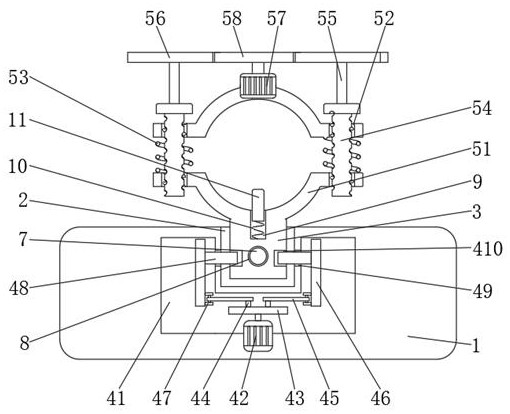

Image

  • CNC (Computer Numerical Control) machining and positioning device for template workpiece
  • CNC (Computer Numerical Control) machining and positioning device for template workpiece
  • CNC (Computer Numerical Control) machining and positioning device for template workpiece

Examples


Embodiment Construction

[0020] The technical solutions of the present invention will be clearly and completely described below with reference to the embodiments. Obviously, the described embodiments are only a part of the embodiments of the present invention, rather than all the embodiments. Based on the embodiments of the present invention, all other embodiments obtained by those of ordinary skill in the art without creative efforts shall fall within the protection scope of the present invention.

[0021] like Figure 1-3 As shown in the figure, a CNC machining positioning device for a template workpiece includes a worktable 1, a chute 2, a slider 3, a positioning assembly 4 and a clamping assembly 5. A chute 2 is opened on one side of the inner wall of the worktable 1. The chute A sliding block 3 is slidably connected to the inner wall of one side of 2, and a positioning assembly 4 is fixed on the inner wall of one side of the sliding block 3 and the chute 2; , the rotating plate 45, the connectin...


PUM


Abstract

The invention discloses a CNC (Computer Numerical Control) machining and positioning device for a template workpiece. The CNC machining and positioning device for the template workpiece comprises a connecting plate, a sliding groove, a sliding block, positioning assemblies and a clamping assembly, wherein the sliding groove is formed in the inner wall of one side of a workbench; the sliding blockis slidably connected to the inner wall of one side of the sliding groove; the positioning assemblies are fixed to the sliding block and the inner wall of one side of the sliding groove; each positioning assembly comprises a mounting groove, a second motor, a rotating wheel, a rotating shaft, a rotating plate, a connecting plate, a rotating lug block, a positioning rod, a guide hole and a positioning groove; and the mounting hole is formed in the inner wall, located below the sliding groove, of the connecting plate. The machining precision is improved, and the production quality of workpiecesis facilitated; and the clamping assembly is further adopted, so that the workpiece can be automatically clamped, the manual assistance is reduced, the working efficiency is improved, the workload ofworkers is reduced, and the working efficiency is improved.

Description

technical field [0001] The invention relates to the field of template workpiece processing equipment, in particular to a template workpiece CNC machining positioning device. Background technique [0002] Workpiece, a product part in the manufacturing process; also called parts, work pieces, courseware, hardware, etc., and the workpiece can be made by CNC machining, and CNC machining usually refers to computer digital control precision machining, CNC machining lathes , CNC machining and milling machines, CNC machining boring and milling machines, etc., and CNC machining usually requires positioning devices for processing, but the existing CNC machining positioning devices for template workpieces generally only position positioning, while template workpieces need shape positioning during processing, and sometimes require staff Manual positioning leads to inaccurate positioning of the workpiece, substandard production quality of the workpiece, waste of production costs, and man...

Claims


Application Information

Patent Timeline
IPC IPC(8): B23Q3/06
CPCB23Q3/062
Inventor 刘英伟陈彪张志进谭志勇
Owner 武汉普泰金属制造技术有限公司
Learn More