Novel thermal deformation injection mold

An injection mold, thermal deformation technology, applied in cleaning methods and appliances, chemical instruments and methods, cleaning methods using gas flow, etc., can solve problems such as damage to injection molded products

Inactive Publication Date: 2020-12-08
王芹
View PDF6 Cites 3 Cited by
  • Summary
  • Abstract
  • Description
  • Claims
  • Application Information

AI Technical Summary

Problems solved by technology

[0005] The purpose of the present invention is to solve the problem that most traditional injection molds are easy to cause damage to injec

Method used


Image

  • Novel thermal deformation injection mold
  • Novel thermal deformation injection mold
  • Novel thermal deformation injection mold

Examples


Embodiment 1

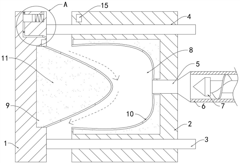
[0026] Such as Figure 1-4 As shown, a new thermal deformation injection mold includes a movable mold 1 and a fixed mold 2. The upper and lower ends of the inner wall of the movable mold 1 are fixedly connected with a plurality of horizontal positioning rods 3, and the side wall of the fixed mold 2 is provided with A plurality of positioning holes 4 corresponding to the positioning rods 3 one by one, the positioning rods 3 are slidingly connected to the positioning holes 4, the side wall of the fixed mold 2 is provided with an injection hole 5, the injection hole 5 is fixedly connected with an injection head 6, and the injection head 6 Be provided with turning roller 7 inside, all above are prior art.

[0027] The inner side wall of the fixed mold 2 is provided with a core groove 8, which forms a die. The inner side wall of the movable mold 1 and the inner side wall of the core groove 8 are all provided with a liquid tank 9, and each liquid tank 9 is filled with an electrorheo...

Embodiment 2

[0037] Such as Figure 5 As shown, the difference between this embodiment and Embodiment 1 is that a plurality of magnetic vibrating blocks 22 are fixedly embedded on the side wall of the memory metal thin layer 10, and a magnetic driving block is fixedly embedded on the side wall of the rotating roller 7. twenty three.

[0038] In this embodiment, the rotating roller 7 is always in a rotating state during the injection molding process, which will drive the magnetic drive block 23 to rotate rapidly. At this time, the magnetic force between the multiple magnetic vibration blocks 22 and the magnetic drive block 23 is constantly changing, so the magnetic vibration The block 22 will vibrate, and a plurality of magnetic vibration blocks 22 are arranged at the corners of the deformed memory metal thin layer 10, which can promote the full filling of the plastic solution.


PUM


Abstract

The invention belongs to the field of injection molds, and particularly relates to a novel thermal deformation injection mold. The injection mold comprises a movable mold body and a fixed mold body. Aplurality of horizontally-arranged positioning rods are fixedly connected to the upper end and the lower end of the inner side wall of the movable mold body, a plurality of positioning holes in one-to-one correspondence with the positioning rods are formed in the side wall of the fixed mold body, and the positioning rods are slidably connected with the positioning holes. An injection molding holeis formed in the side wall of the fixed mold body and fixedly communicates with an injection molding head, a rotating roller is arranged in the injection molding head, a core groove is formed in theinner side wall of the fixed mold body, liquid containing grooves are formed in the inner side wall of the movable mold body and the inner side wall of the core groove, electrorheological fluid is contained in each liquid containing groove, and a memory metal thin layer is hermetically connected to a groove opening of each liquid containing groove. Core blocks are formed between the memory metal thin layers and the movable mold body, and a thermoelectric power generation piece is fixedly embedded in the inner side wall of the movable mold body and electrically connected with the electrorheological fluid. The axis of an air outlet hole channel is obliquely arranged downwards, it can be guaranteed that sprayed air directly enters the space between the movable mold body and the fixed mold body, dust in the air is removed, and the dust removal effect is better.

Description

technical field [0001] The invention belongs to the field of injection molds, in particular to a novel thermal deformation injection mold. Background technique [0002] There are many ways to process rubber and plastic products. Injection molding is one of the more common methods. In the injection molding process, an injection mold is required to inject the plastic solution into the mold through the injection head, and then the solidified product is cooled. The demoulding process is relatively simple. [0003] In most traditional injection molds, the inner cores of the movable mold and the fixed mold are mostly made of hard materials with a certain shape and structure. After the injection molding is completed and cooled, the injection molded product will still adhere to the inner wall of the mold. The ejection device can be used to demould the injection molded product. The demoulding time needs to be strictly controlled during demoulding. The demoulding can only be performe...

Claims


Application Information

Patent Timeline
IPC IPC(8): B29C45/26B29C45/14B29C33/30B29C33/72B29C33/42B29C45/40B29C33/76B08B5/02
CPCB08B5/02B29C33/72B29C33/76B29C45/14B29C45/2606B29C45/263B29C45/40
Inventor 王芹
Owner 王芹
Why Eureka
Try Eureka