
Two-dimensional code marking system

A two-dimensional code and code scanning technology, applied in typewriters, printing devices, printing, etc., can solve the problems of labor cost waste, worker injury, low efficiency, etc., and achieve the effect of improving processing efficiency and high degree of automation

Inactive Publication Date: 2020-12-08
江苏创励安科技有限公司
View PDF11 Cites 3 Cited by
  • Summary
  • Abstract
  • Description
  • Claims
  • Application Information

AI Technical Summary

Problems solved by technology

The existing two-dimensional code marking equipment mainly relies on manual loading and unloading and flipping, which is prone to unexpected situations such as worker injury or product damage, which greatly wastes labor costs and extremely low efficiency

Method used


Image

  • Two-dimensional code marking system
  • Two-dimensional code marking system
  • Two-dimensional code marking system

Examples


Embodiment 1

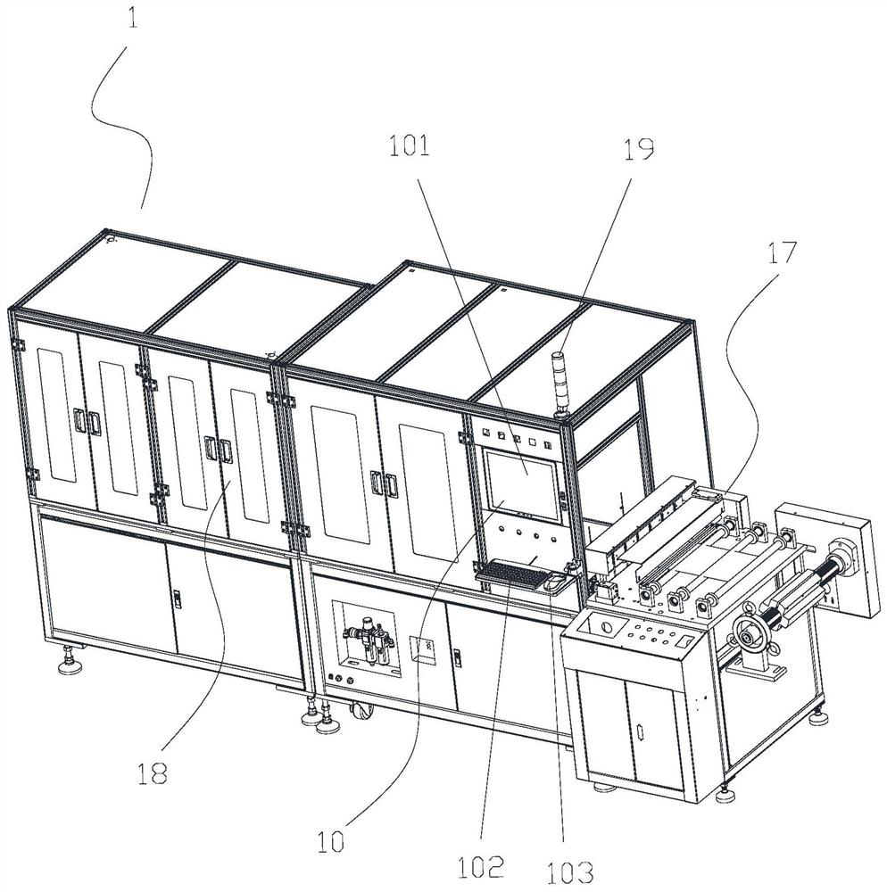
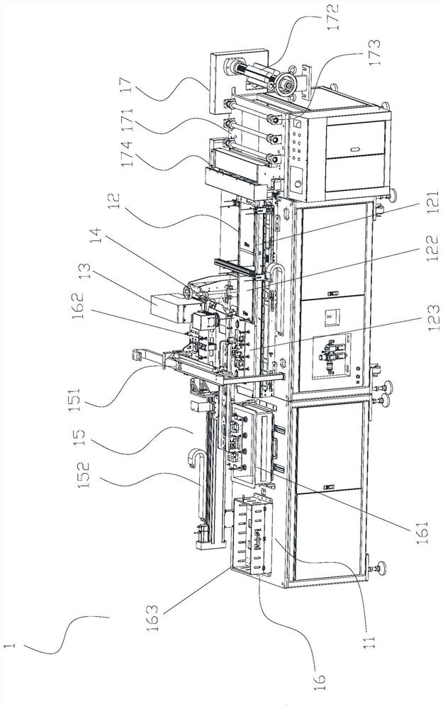
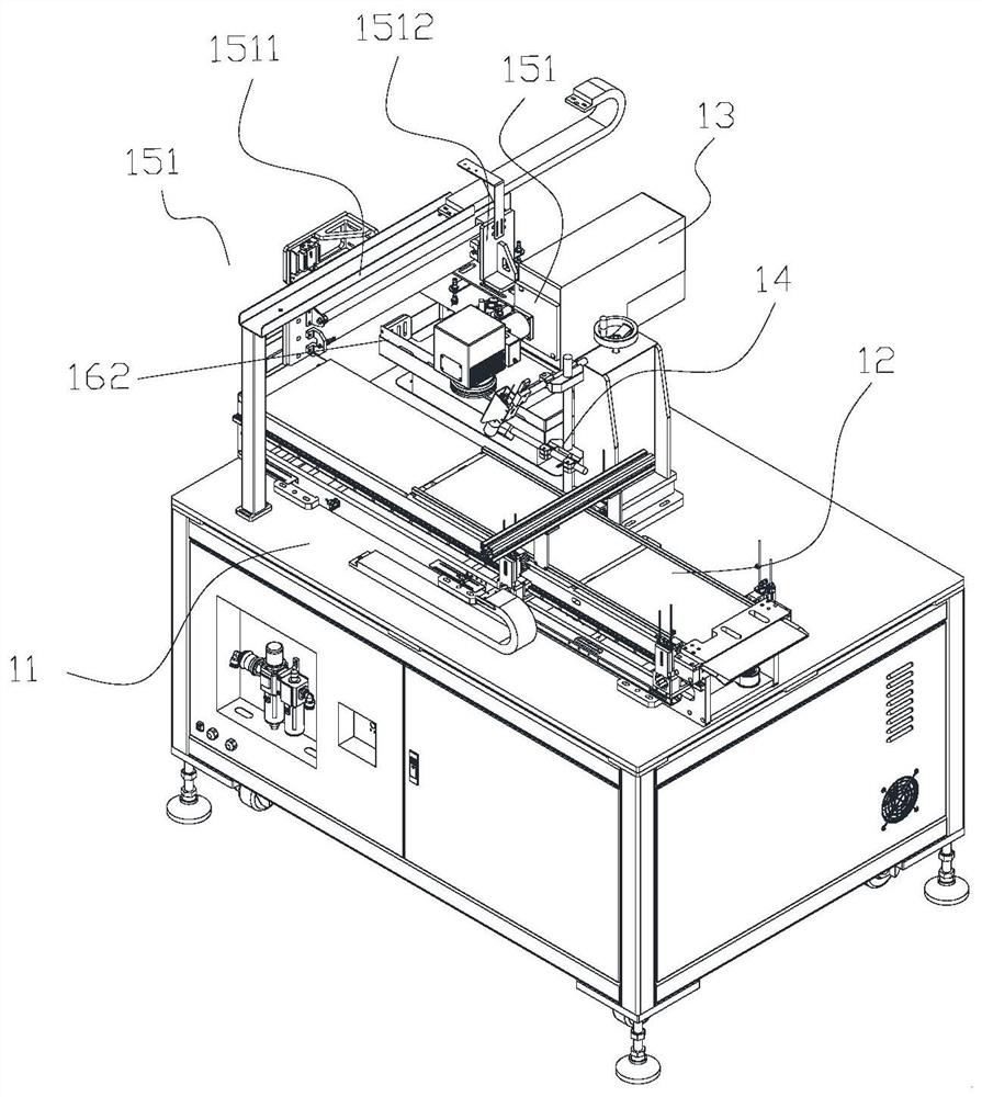
[0041] Example 1 see Figure 1 to Figure 17 , in a two-dimensional code marking system of this embodiment, the two-dimensional code marking system 1 includes a control device, a workbench 11 and a product delivery unit 12, a laser marking unit 13, a code scanning unit The detection unit 14 , the conveying unit 15 and the magazine 16 , the product conveying unit 12 , the laser coding unit 13 , the code scanning detection unit 14 and the conveying unit 15 are electrically connected to the control device 10 .

[0042] See figure 2 and Figure 5 , the product conveying unit 12 includes a linear track 121 , and a detection station 122 and a handling station 123 are arranged on the linear track 121 .

[0043] See Figure 5 to Figure 7 , both sides of the linear track 121 are respectively provided with slide rail mechanisms 125, and the slide rail mechanisms 125 on both sides are respectively provided with clamping jaw assemblies 126 for moving products. The gripper assembly inc...

Embodiment 2

[0073] See Figure 18 , in a two-dimensional code marking system of this embodiment, the two-dimensional code marking system 2 includes a control device, a workbench 21 and a product delivery unit 22 located on the workbench 21, a laser marking unit 23, a code scanning unit The detection unit 24, the conveying unit 25 and the material box, the product conveying unit 22, the laser coding unit 23, the code scanning detection unit 24 and the conveying unit 25 are electrically connected to the control device.

[0074] Please continue to see Figure 18 , the product conveying unit 22 includes a linear track 221 , and a detection station 222 and a handling station 223 are arranged on the linear track 221 .

[0075] Please continue to see Figure 18 , the material box 26 is arranged on the side of the handling unit 25, including an OK material box 261 for placing qualified products and an NG material box 262 for placing unqualified products. Preferably, a slide rail is provided be...


PUM


Abstract

The invention discloses a two-dimensional code marking system, and relates to the technical field of automatic marking equipment. The two-dimensional code marking system comprises a control device anda workbench, and further comprises a product conveying unit, a laser coding unit, a code scanning detection unit, a carrying unit and a material box which are arranged on the workbench, wherein the product conveying unit, the laser coding unit, the code scanning detection unit and the carrying unit are electrically connected with the control device. The two-dimensional code marking system is highin automation degree, automatic plate cutting, automatic coding, automatic code scanning, automatic sorting and carrying and other operations can be conducted, the machining efficiency is greatly improved, and the two-dimensional code marking system is suitable for industrial application and popularization.

Description

technical field [0001] The invention relates to the technical field of automatic marking equipment, in particular to a two-dimensional code marking system. Background technique [0002] There are many types of FPC boards, large production volume, complex process flow, intensive production equipment types and manpower requirements. In order to meet the development needs of its production and intelligent control, it is necessary to import MES (manufacturing enterprise production process execution system) or SFIS (site information integration) system) and other intelligent system software for management. The intelligent system software can monitor the entire production process from raw materials entering the factory to product warehousing, record the materials and equipment used in the production process, the data and results of product testing, and the production time and personnel of each process. At the same time, the production progress of the production site, target achie...

Claims


Application Information

Patent Timeline
Patent Type & Authority Applications(China)
IPC IPC(8): B41J3/01B41J2/435B41J11/66B23K26/362
CPCB23K26/362B41J2/435B41J3/01B41J11/66B23K2101/007
Inventor 关艳徐鹏辉闫海冰
Owner 江苏创励安科技有限公司
Learn More