Building lighting device with angle convenient to adjust

A technology for adjusting the angle and architecture, applied in portable lighting devices, lighting devices, non-electric lighting devices, etc., can solve the problems of inability to illuminate the lighting, low light guide effect, affecting the light collection of the light guide plate, etc., to improve the lighting efficiency. Effect

Inactive Publication Date: 2020-12-08
安徽世勤建筑劳务有限公司
View PDF1 Cites 1 Cited by
  • Summary
  • Abstract
  • Description
  • Claims
  • Application Information

AI Technical Summary

Problems solved by technology

[0004] The purpose of the present invention is to solve the shortcomings in the prior art, such as: 1. The light receiving range of the existing lighting device is limited, and the irradiation position of the light will change in different time periods every day, so the light may not be irradiated in some time periods. On the daylighting device, such a daylighting device cannot effectively daylight and affect people's lives. 2. The installation of the daylighting device in the prior art still uses bolts, which is very inconvenient to install and very cumbersome to operate. It takes a lot of time to twist multiple bolts , so the efficiency of disassembly and installation

Method used


Image

  • Building lighting device with angle convenient to adjust
  • Building lighting device with angle convenient to adjust
  • Building lighting device with angle convenient to adjust

Examples


Embodiment Construction

[0033] The following will clearly and completely describe the technical solutions in the embodiments of the present invention with reference to the accompanying drawings in the embodiments of the present invention. Obviously, the described embodiments are only some, not all, embodiments of the present invention. Based on the embodiments of the present invention, all other embodiments obtained by persons of ordinary skill in the art without creative efforts fall within the protection scope of the present invention.

[0034] In describing the present invention, it should be understood that the terms "upper", "lower", "front", "rear", "left", "right", "top", "bottom", "inner", " The orientation or positional relationship indicated by "outside", etc. is based on the orientation or positional relationship shown in the drawings, and is only for the convenience of describing the present invention and simplifying the description, rather than indicating or implying that the referred dev...


PUM


Abstract

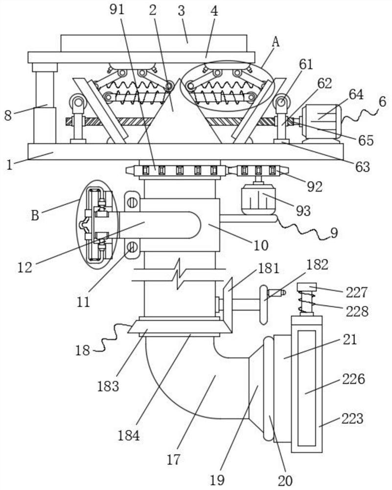
The invention discloses a building lighting device with the angle convenient to adjust, and relates to the technical field of building lighting devices. The building lighting device comprises a supporting plate, a light guide pipe and a top plate, wherein a triangular light guide plate is fixedly connected to the upper surface of the supporting plate; light reflecting plates are arranged on the left side and the right side of the triangular light guide plate and hinged to the upper surface of the supporting plate; a cleaning mechanism is arranged between the light reflecting plates and the triangular light guide plate and fixedly connected to the lower surface of the top plate; and a water tank is arranged on the upper surface of the top plate. According to the building lighting device, byarranging a first steering mechanism, the first steering mechanism can drive a connecting pipe to rotate during work, the connecting pipe can rotate in a third shaft sleeve, and therefore the supporting plate can rotate to adjust the positions of the triangular light guide plate and the light reflecting plates; and two sets of extrusion rollers in an adjusting mechanism can get close to each other or get away from each other, and therefore the light reflecting plates can be extruded, the angles of the light reflecting plates are changed, the light receiving angles of the light reflecting plates can be changed, and the lighting efficiency is greatly improved.

Description

technical field [0001] The invention relates to the technical field of architectural daylighting devices, in particular to an architectural daylighting device that facilitates angle adjustment. Background technique [0002] The building lighting device is to obtain a good lighting environment and save energy. The measures taken to arrange various forms of lighting openings (windows) on the building envelope (walls, roofs) guide the external light into the room and expand the larger area. The range of light and the duration of light can play a very good role, especially in densely populated locations. [0003] A Chinese patent discloses "a building lighting device" (patent number: CN201811033326.9), which records that "the light reflection system in the building lighting device provided by an embodiment of the present invention can track the sun and The sunlight is reflected for the first time, the second specular reflection unit receives the sunlight reflected by the light ...

Claims


Application Information

Patent Timeline
IPC IPC(8): F21S11/00F21V5/02F21V7/05F21V8/00F21V14/04F21V1/08F21V1/12F21V17/02F21V21/30B08B1/00B08B1/04B08B3/02
CPCB08B1/001B08B1/04B08B3/02F21S11/002F21S11/007F21V1/08F21V1/12F21V5/02F21V7/05F21V14/04F21V17/02F21V21/30F21V2200/40
Inventor 朱凯强
Owner 安徽世勤建筑劳务有限公司
Why Eureka
Try Eureka