
Motion state estimation method and device

A motion state and azimuth technology, applied in the field of Internet of Vehicles, can solve the problems of IMU error accumulation, large motion state error, and susceptibility to electromagnetic interference, etc.

Pending Publication Date: 2020-12-08
HUAWEI TECH CO LTD
View PDF8 Cites 2 Cited by
  • Summary
  • Abstract
  • Description
  • Claims
  • Application Information

AI Technical Summary

Problems solved by technology

However, the IMU has the disadvantage of error accumulation and is susceptible to electromagnetic interference
It can be seen that the error of the motion state of the vehicle measured by the prior art is relatively large, how to obtain a more accurate motion state of the sensor is a technical problem being studied by those skilled in the art

Method used


Image

  • Motion state estimation method and device
  • Motion state estimation method and device
  • Motion state estimation method and device

Examples


Embodiment Construction

[0081] Embodiments of the present invention will be described below with reference to the drawings in the embodiments of the present invention.

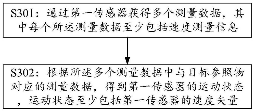
[0082] See image 3, is a motion state estimation method provided by an embodiment of the present invention. The execution subject of this method may be a sensor system or a fusion sensing system or a planning / control system integrating the above systems, such as an assisted driving or automatic driving system, etc., and may be software or In the form of hardware (such as a motion state estimation device that is connected to corresponding sensors via wireless or wired or integrated), the following different execution steps can be implemented in a centralized or distributed manner.

[0083] The method includes but is not limited to the following steps:

[0084] Step S301: Obtain a plurality of measurement data through the first sensor, wherein each measurement data includes at least speed measurement information.

[0085] Specifical...


PUM


Abstract

The embodiment of the invention provides a motion state estimation method and device, and the method comprises the steps: obtaining a plurality of measurement data through a first sensor, wherein eachmeasurement data at least comprises speed measurement information; and according to the measurement data corresponding to the target reference object in the plurality of measurement data, obtaining amotion state of the first sensor, the motion state at least comprising a speed vector of the first sensor. By adopting the embodiment of the invention, the more accurate motion state of the first sensor can be obtained.

Description

technical field [0001] The invention relates to the technical field of Internet of Vehicles, in particular to a method and device for estimating the motion state of a sensor. Background technique [0002] In the advanced driving assistant system (Advanced Driving Assistant System, ADAS) or automatic driving (Autonomous driving, AD) system is usually equipped with a variety of sensors, such as radar (Radar) sensors, ultrasonic sensors, vision sensors, etc., to perceive the surrounding environment and target information. Using the information obtained by the above sensors, the functions of classification, identification and tracking of the surrounding environment and objects can be realized. Further, the above information can be used to realize the situation assessment of the surrounding environment and planning control. For example, the track information of the tracking target can be used as a vehicle The input of planning control improves the efficiency and safety of vehicl...

Claims


Application Information

Patent Timeline
IPC IPC(8): G01C25/00
CPCG01C25/00G01C25/005G01S13/589G01S13/60G01S15/588G01S15/60G01S7/41G01S13/867G01S13/931G01S15/931G01S13/865B60W40/105B60W40/107G01S13/86
Inventor 王建国王绪振
Owner HUAWEI TECH CO LTD
Learn More